Terminating the headphone and microphone jacks was the last set of main actions needed for the interior fuselage electrical system. What remained were cable lacing and those connections left for when the engine is mounted.

 The center console cover plate and rear face of the armrest are the locations for the jacks.

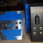 The mounting components for the front plate are shown on the left. The rear face mock-up is on the right.
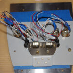
 The inner side of each jack location contains a backer plate with holes for the soldered wires and auxiliary devices. On the front plate are spaces for the Bose LEMO jacks and an auxiliary audio input. The rear face includes a USB power connector with two ports.
 Here the front cover plate is shown under the control quadrant. Note in this photo the hole for the auxiliary audio input has not yet been drilled.

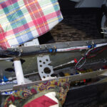 The console parts were laid on their side to trim ins a straight line as shown on the right. The interior tunnel wiring with fuel pump and transducer wiring is shown on the left.

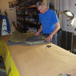 Preparing the headliner material for covering the fiberglass template included steaming to remove wrinkles and cutting to approximate size. The attempt to cover the fiberglass with material once spray adhesive applied was a total disaster (no photos shown due to the embarassment factor). Fortunately the fiberglass templates were recovered. The covering job will be left for professionals.
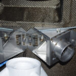
 Final configuration of the push-pull cables for the fore heater box, rear heater box, and oil cooler valve were also completed on both the interior and exterior side. These were McFarlane MCU224-xx slip resistant cables in all cases.
 The main ground wire under the pilot seat was encased in 7/16″ fuel line to further protect against chaffing against bulkhead parts. This was probable not necessary given the clearance, but extra precautions for this critical matter were taken.