I started the day wanting to utilize the fantastic CherryMAX and CherryLOCK riveters loaned from my brother on the forward floor pans. However, the offset head of the CherryMAX is rated for sizes 4,5 and 6 rivets, it does not want to work on generic LP4-4 rivets. The mechanism operates properly, just does not grip the smooth shafts of the generic rivets properly. On test stock, a geniune CherryMAX rivet worked perfectly. I may go out to Aircraft Spruce to purchase a few just for practice.
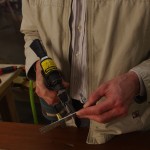 Here the CherryMAX rivet puller is attempted with an LP4-4 rivet. No joy.
I then decided to start building a prototype bracket for the Comant CI-158C VOC/LOC/GS antenna. The plan from way-back when building the vertical stabilizer (VS) was locate the antenna under the top fiberglass dome. I had previously added a 5/8″ black conduit and reinforcing plate to this location on the VS. Now the antenna puck and whip antennas are physically available for inspection, I probably would relocate some of the holes to make assembly easier. Anyway the mock-up was started with a piece of 3/4″ red oak to simulate the eventual stock of acetal copolymer (ordered today). The DuPont trademarked material is called Delrin, and differs from the generic acetal by consisting of a monopolymer – somewhat stronger, but considerable more expensive. I had originally thought of using a nylon block, but my technical counselor advised against due to the greater mechanical properties and ability to machine finish the copolymer.
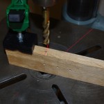 Here the oak board is clamped in the drill press for side drilling a 1/2″ hole. My thought is use an aluminum rod to hold the stainless whip antennas, then secure with a set screw performing double duty as the electrical connection to the integrated puck/balun.
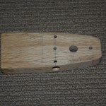 All the main holes are drilled. The final acetal block will have the set screw location tapped for a #10-32 stainless screw.
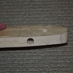 Side view of the raw block. Sanding and fitting inside the upper cavity is next.
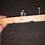
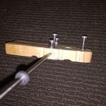 Side view of the fitted block, with mounting and set screws in position. The right photo has the stainless antenna provisionally fit into a 1/2″ wooden dowel. This matches the final use of a drilled aluminum rod to hold the antenna.
At this point the prototype is done – just need to smooth out the lines and measure everything for when the acetal arrives.
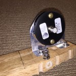
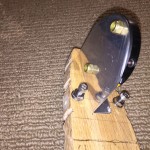 Left and right views of the puck bracket on the oak antenna prototype.
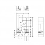 After building the prototype, I laid out a rough diagram of the final product. I never had any drafting skills, but the outcome should be understandable.
