Category Archives: Rv-10 Build Project

Transparencies and Miscellaneous

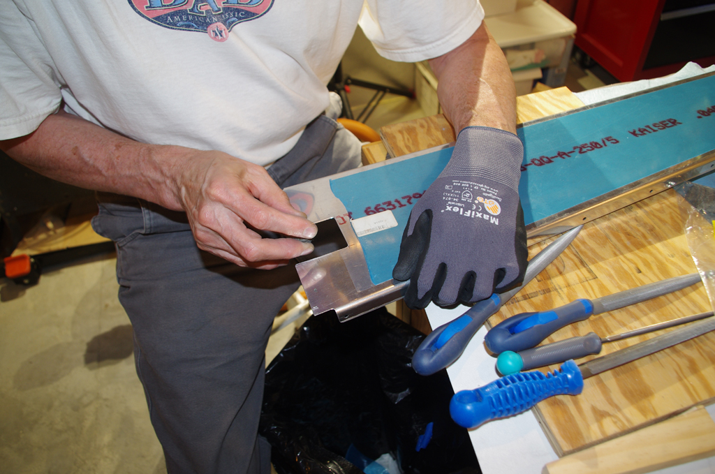
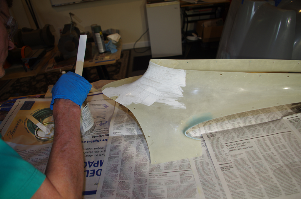
The Lexan/Plexiglass transparencies used for the rear and door windows were bonded with Lord 7475A/D two-part epoxy adhesive.  These parts were trimmed to size and smooth sanded in prior posts.

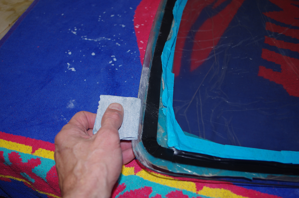
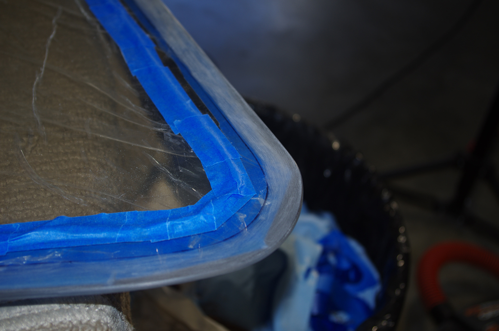
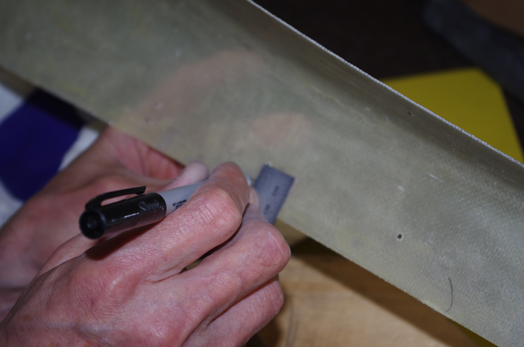
Electrical tape provided protection on the rear windows during roughing the inner surface with 120 grit sandpaper to enhance adhesion.  Then the window frames were taped so excess adhesive could be easily removed.


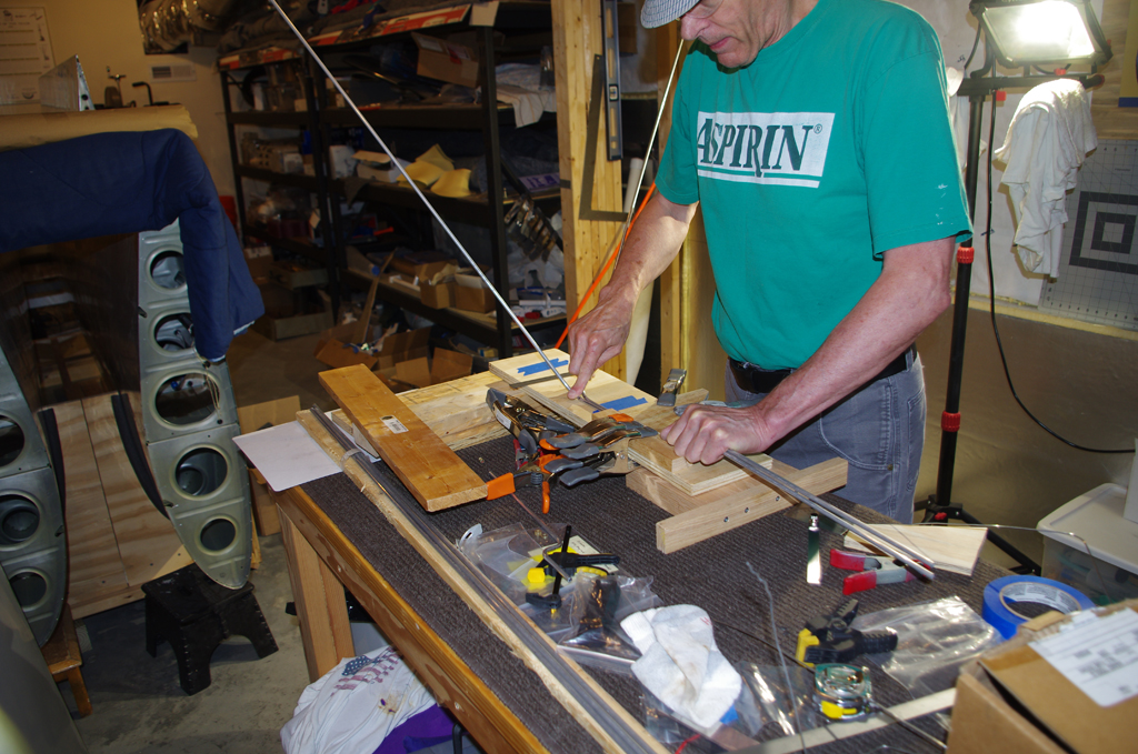
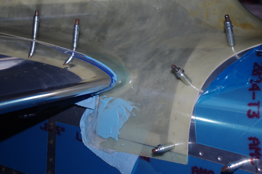
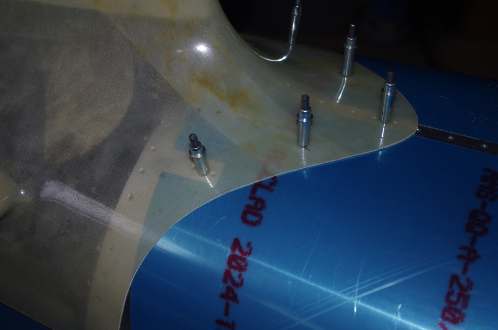
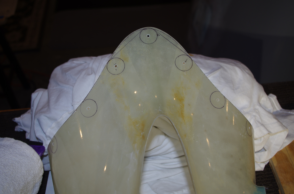
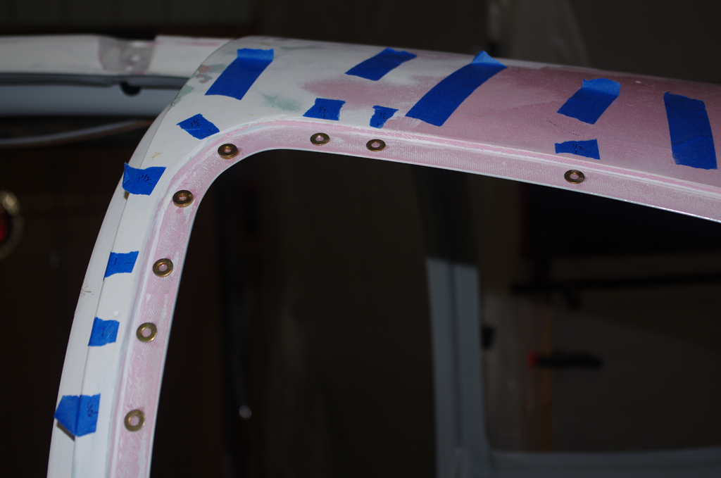
Shims in the form of AN960-10 and AN960-10L washers were placed to bring the window surface to level to -.010 inch of the canopy. This helps with the physical holding of the window, plus will allow for later blending with filler to a smooth transition.


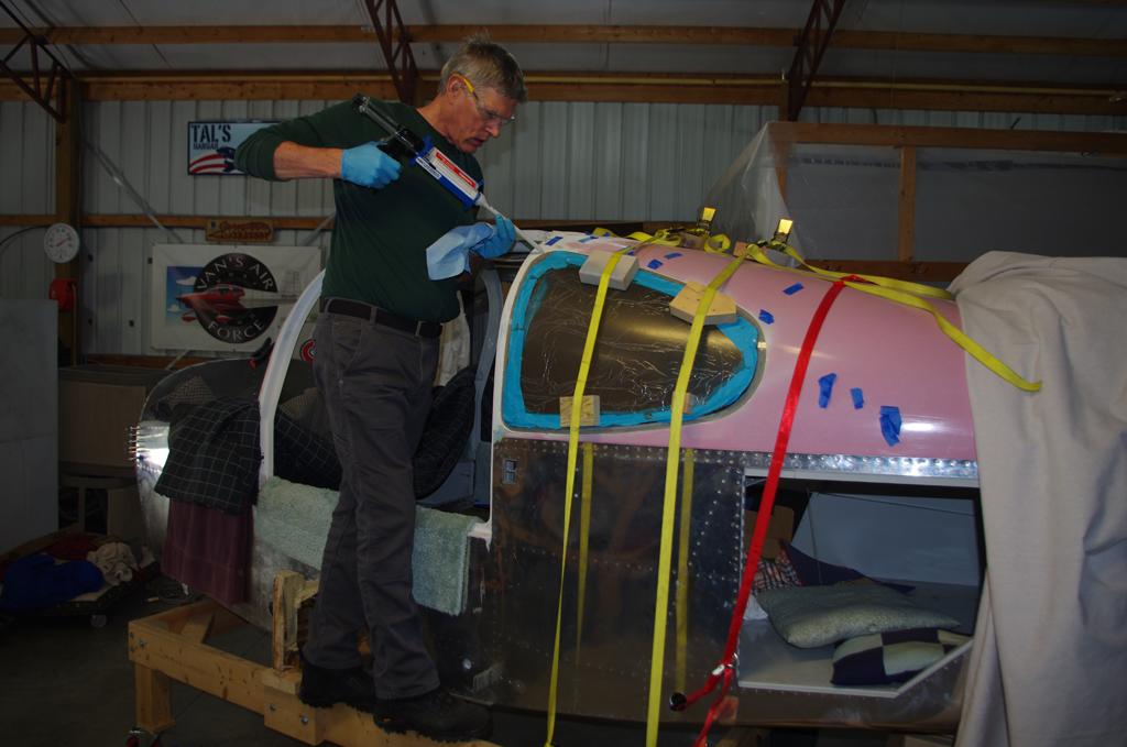
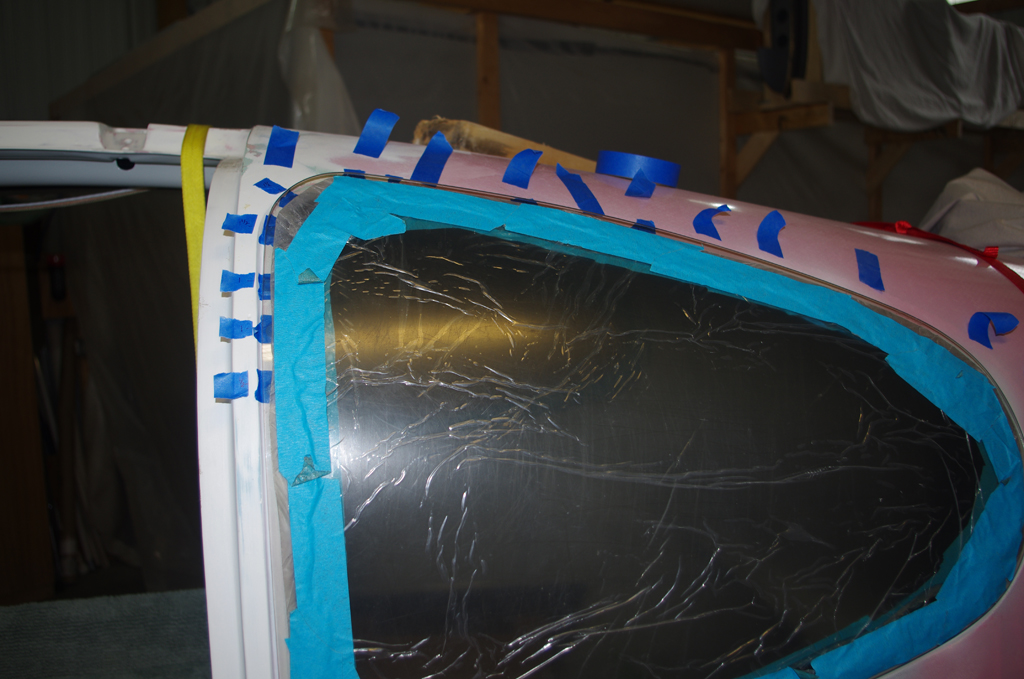
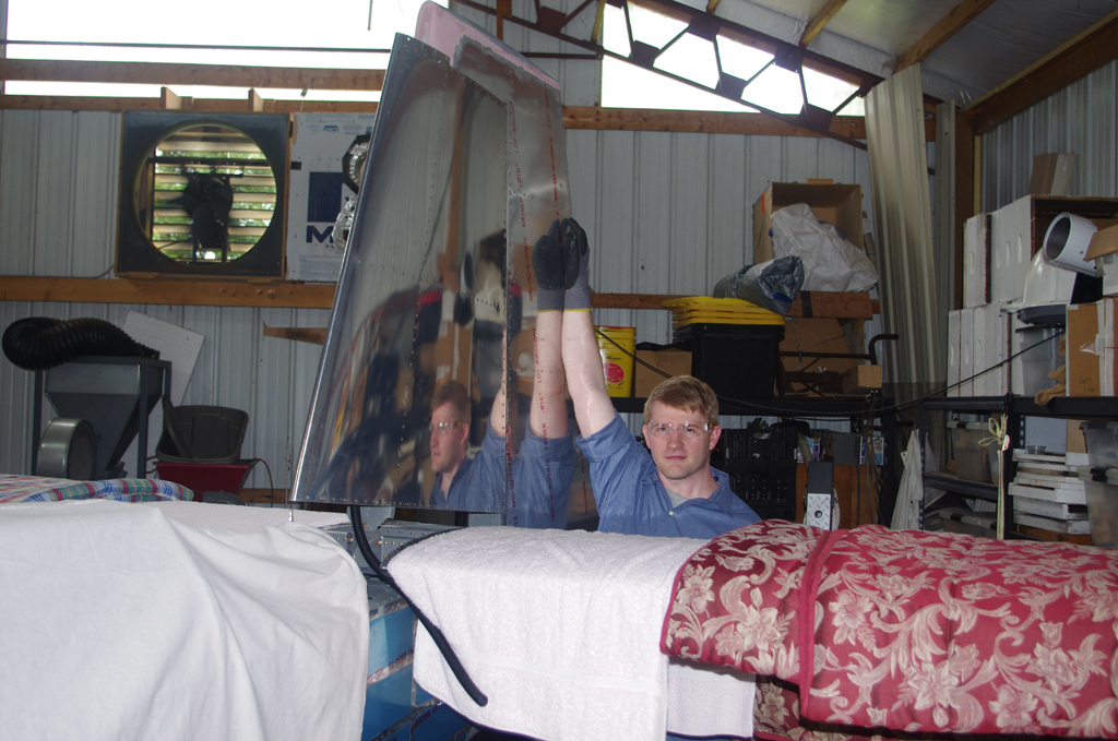
The bonding process was a bit scary – only one shot to get it right.  The reason is the Lord adhesive cures very quickly and is extremely difficult to remove after it sets. Fortunately the rear windows turned out fine.


The same method described above was used on the door windows.  Straps and clamps hold the windows tight to the frame while the adhesive cures.
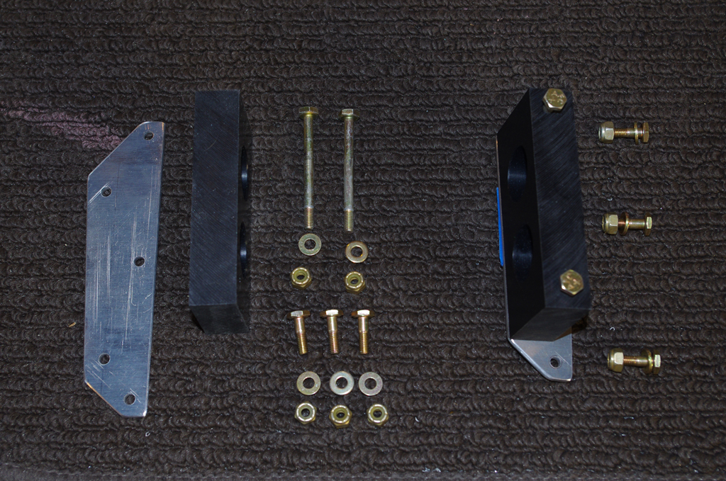
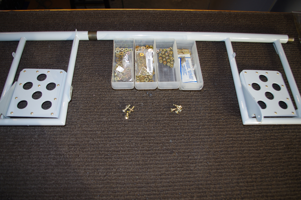
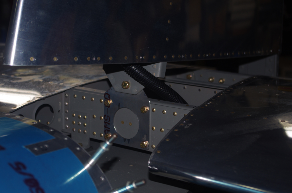


GMU MOUNT BRACKET

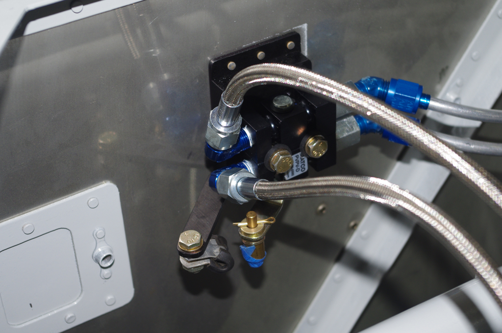
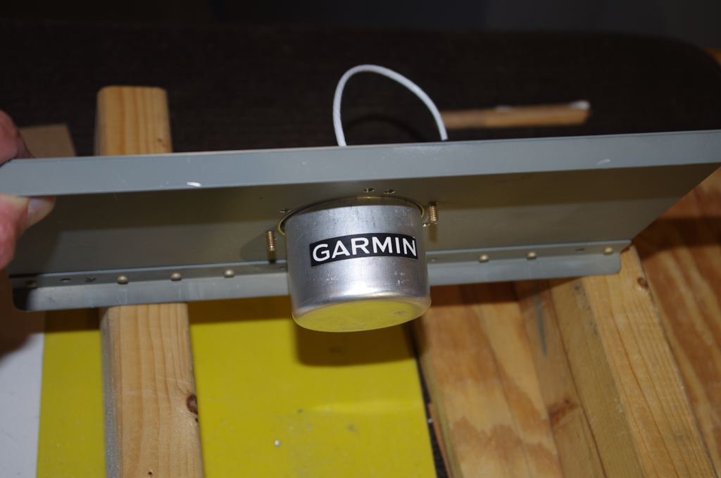
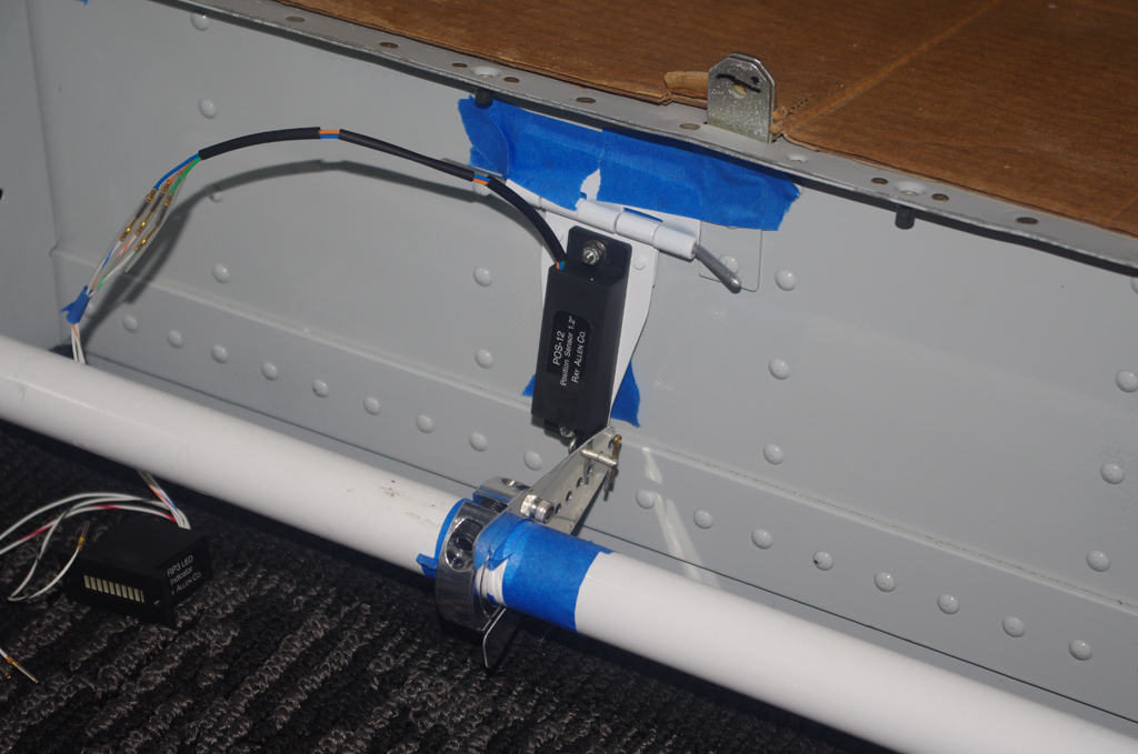
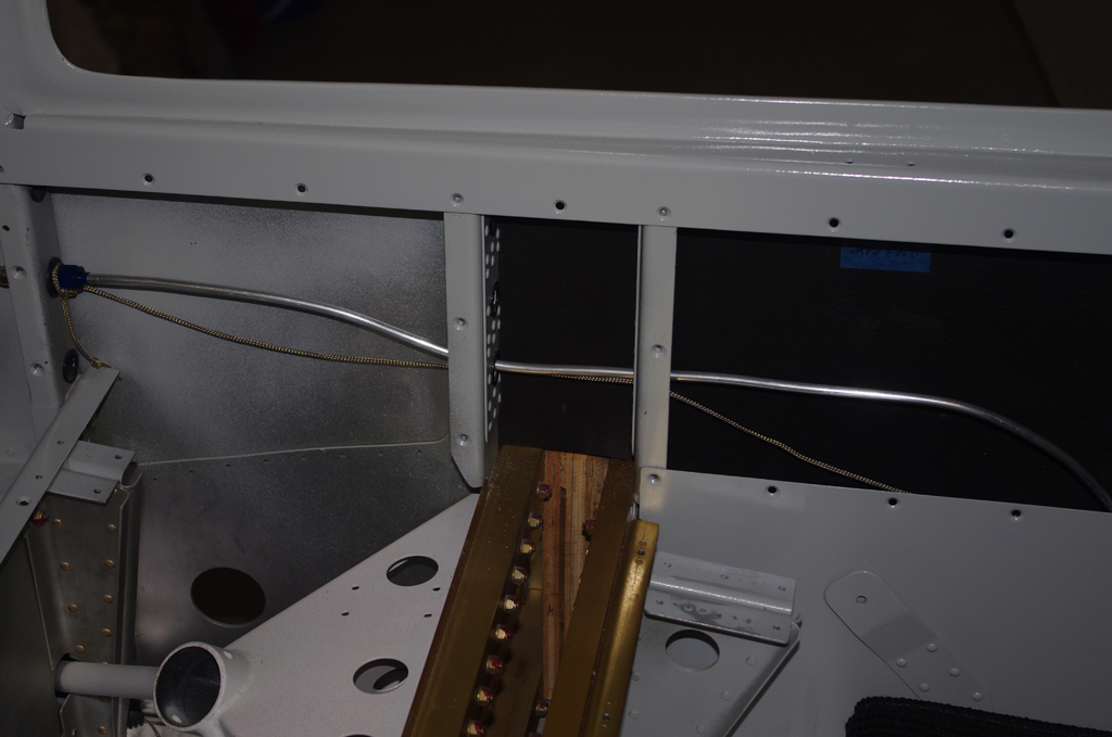
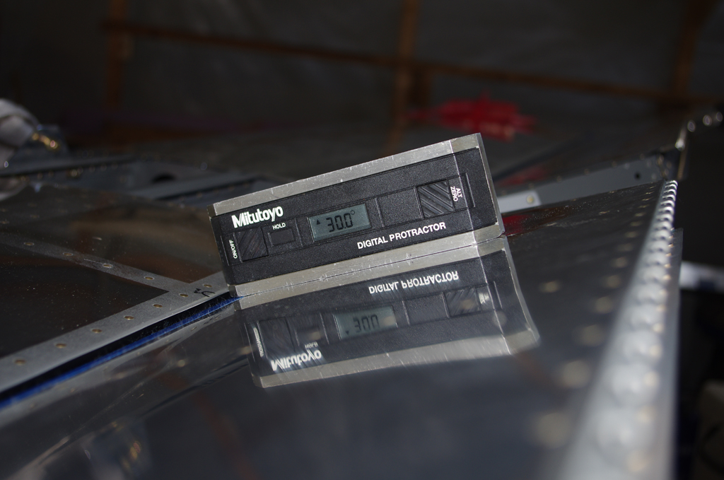
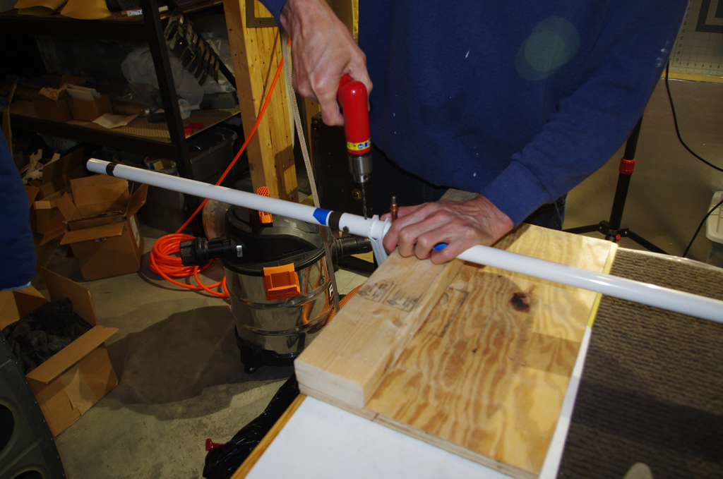
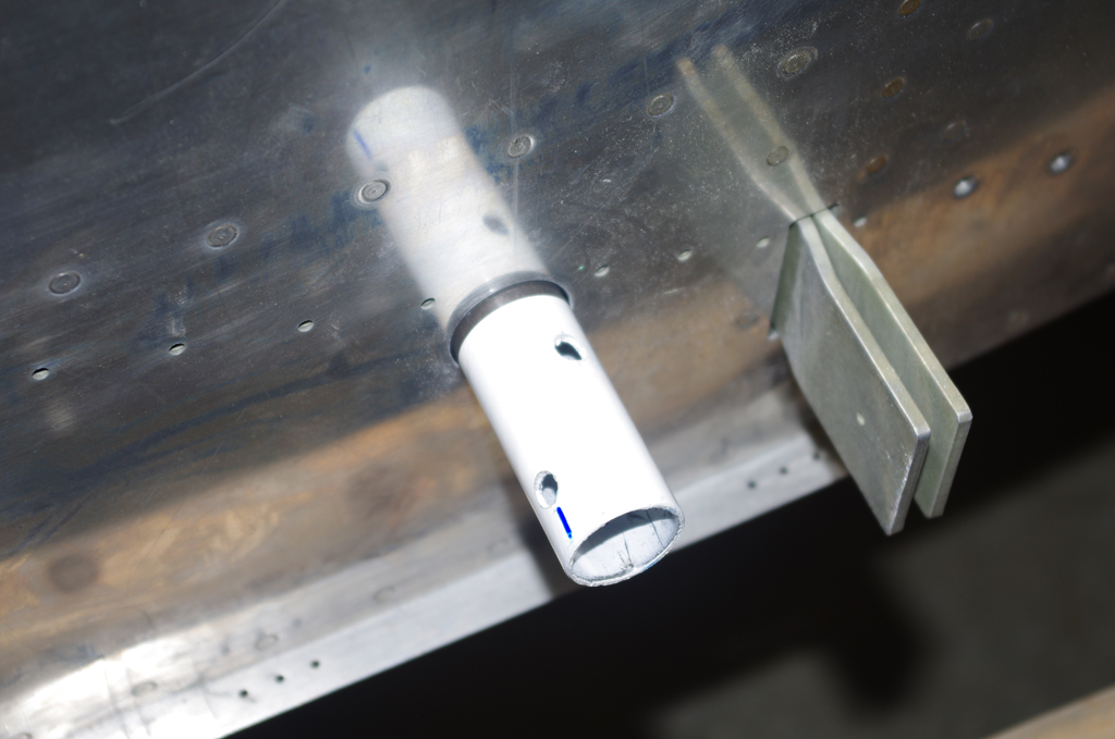
Previously a mounting bracket for the Garmin GMU 22 magnetometer was fabricated for placement in the mid-tail section. The angle of the bracket should be as close to zero degrees level with the fuselage waterline during flight as possible.  It was determined with a digital protractor that the bracket needed to be adjusted about 1.8 degrees down to meet this requirement.

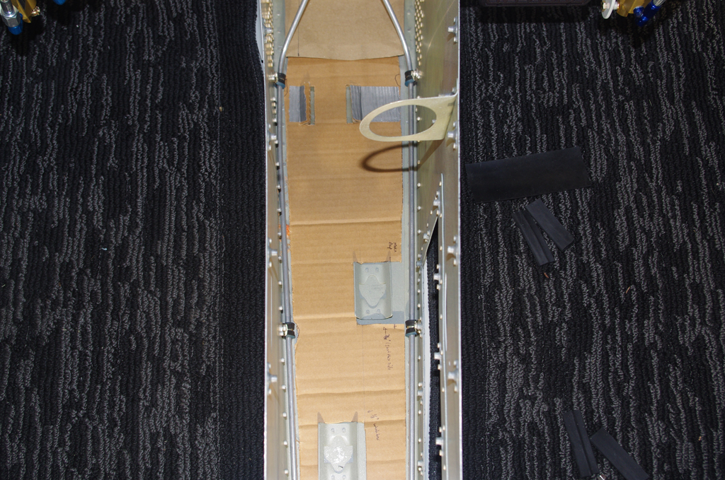
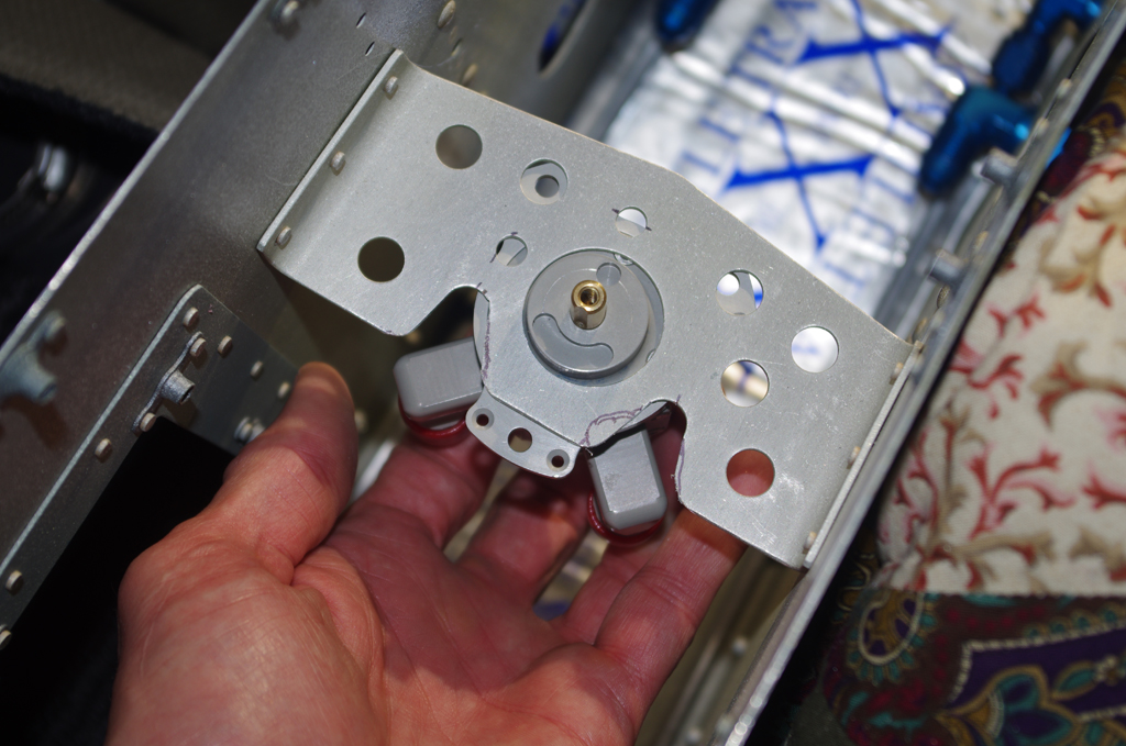
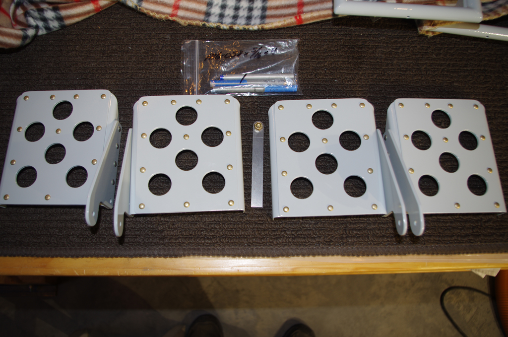
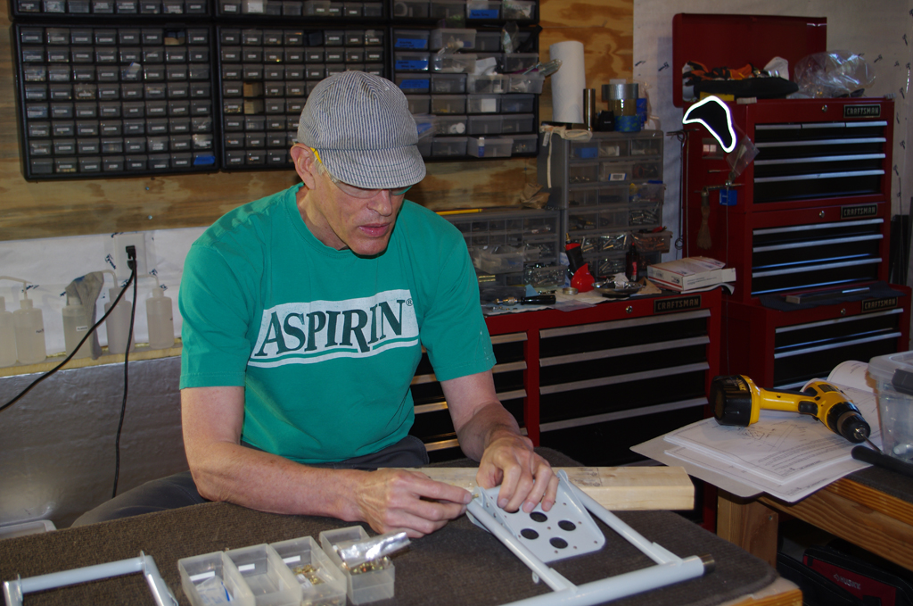
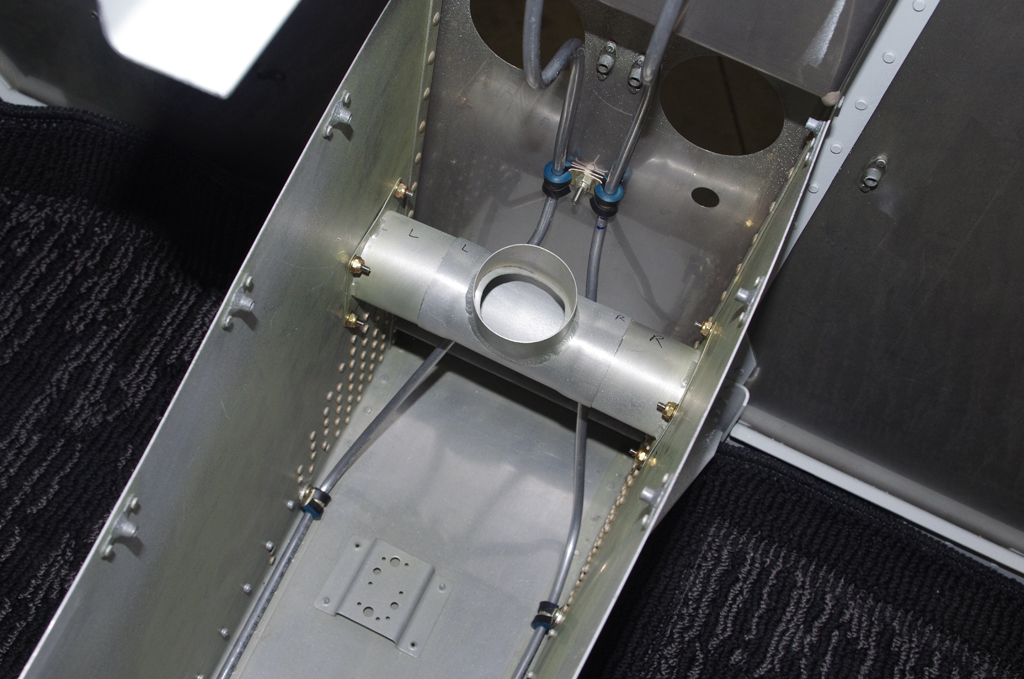
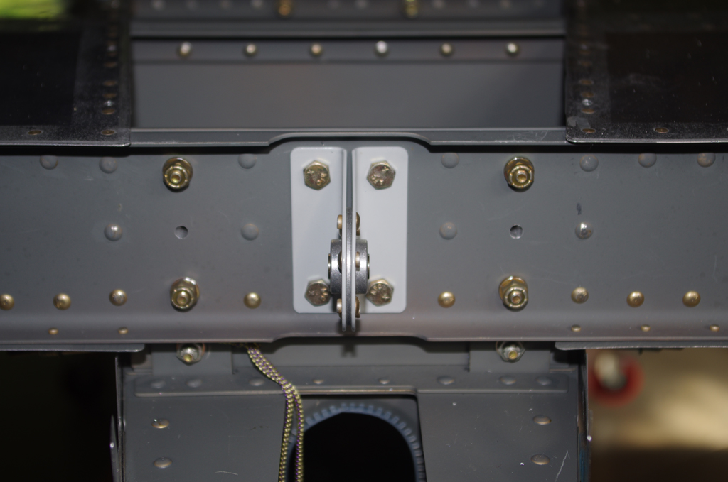
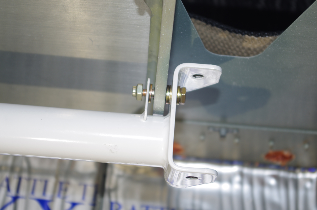
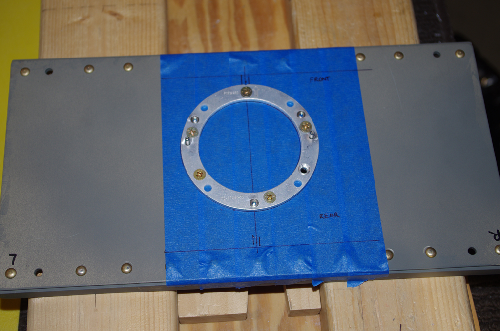
The bracket was constructed so that brass screws adjust the tilt angle of the magnetometer platform to the flight waterline.  More on that adjustment in a later post. Here the GMU bracket is positioned along the plane centerline


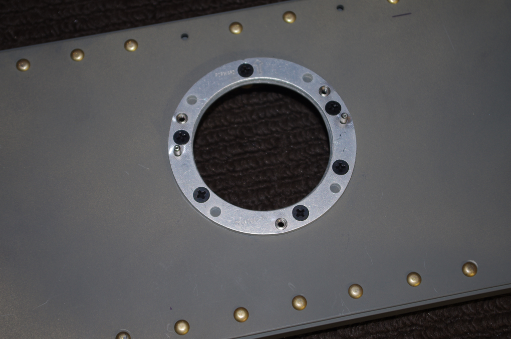
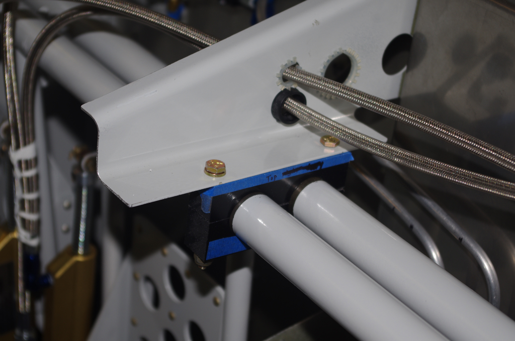
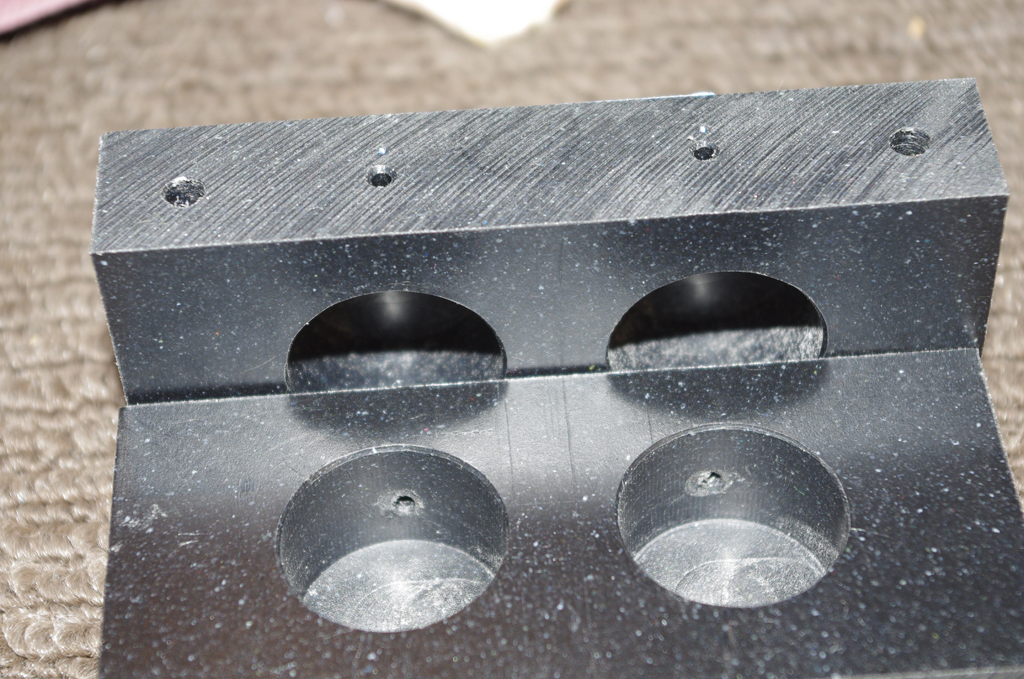
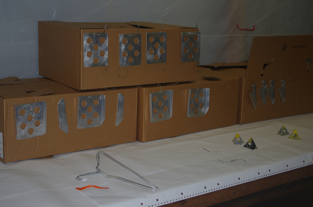
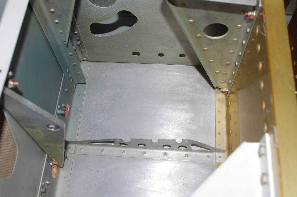
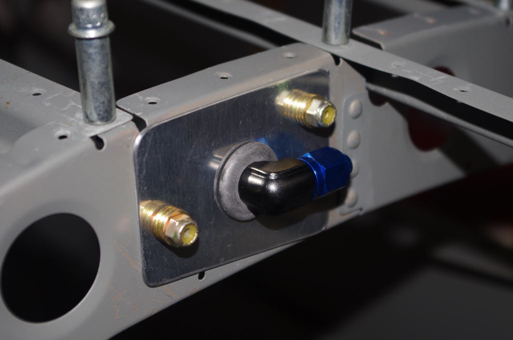
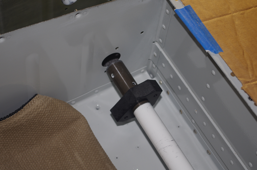
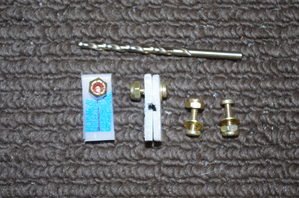
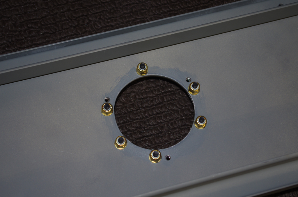
The GMU bracket seen from above and below after priming from the hole drilling.  Note the use of brass screws and stop nuts.  According to vendor specifications, any magnetic components should be at least 2-3 feet from the magnetometer. The location of the bracket in the tail should achieve this goal.


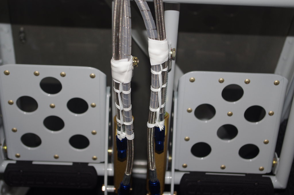
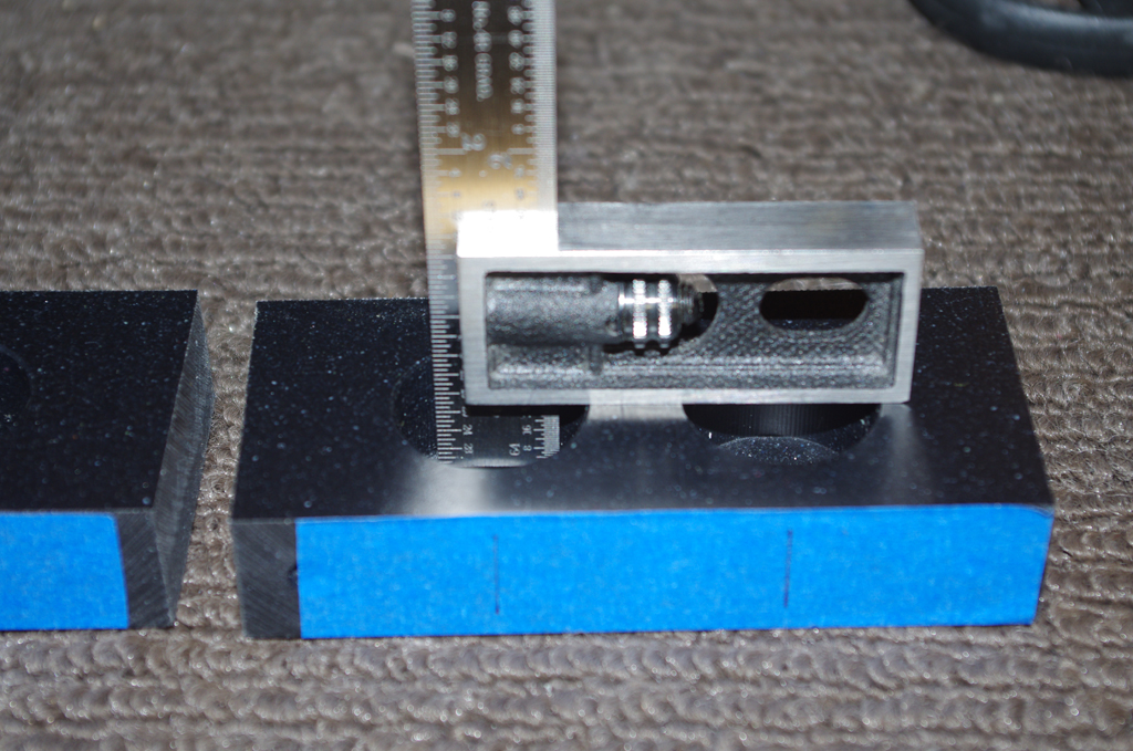
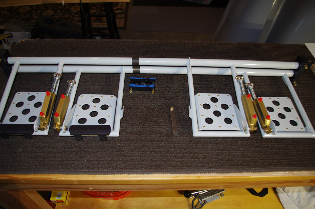
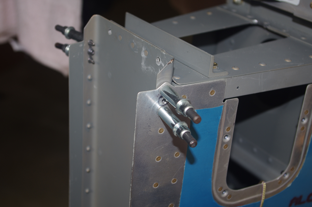
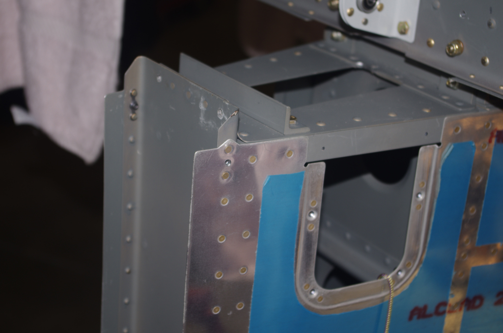
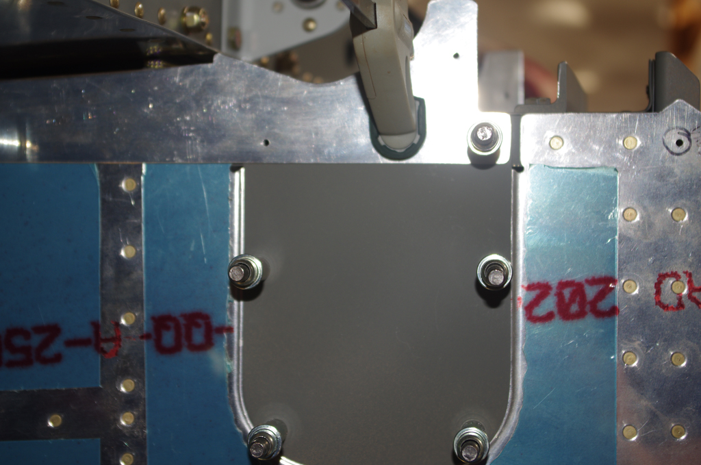
These pictures are the final fit of the GMU bracket to the custom platform.


N190XB 3D Panel

This page makes available a Blender 2.79b file containing a baseline instrument panel configuration for my airplane.  Note: this file and the download page are a work in progress and may be updated/removed at any time.

Empennage Attach (6) and Custom Elements

The latest steps were in completing elements of the empennage attachment sequence. All the actions were of an interim nature, further posts on all elements will follow.

The last hole in the longeron at the rear of the vertical stabilizer required a nutplate install. The rudder had to be off to access the rivets.


Then install the rudder to test fit the cable linkages. The default lengths  in the plans of 1″ on for aft pedal and 2.25″ on the forward pedal did not align the rudder to neutral.  Further adjustments were required.


FLAP POSITION SENSOR

According to literature, many folks recommend using a Ray Allen POS-12 position sensor instead of the default AirWard configuration. A bracket was made earlier for the sensor, then a provisional lever mounted to a 2-piece collar clamp was used to test the throw length and hinge positions.


STATIC LINES

A custom bulkhead configuration of 3/4 rubber grommet, then a push-to-connect pneumatic fitting connected to NPT-AN4 adapter was made for the forward 1/4″ Verstube termination.


The static tube pulled through the cable runs was aluminum instead of plastic.  I wanted to ensure this would never require a replacement after the plane is finished.


A similar fitting configuration was used in the rear for a permanent attachment.  A custom mounting bracket uses the existing lighting hole as a pass-through. Standoffs will hold the plastic lines from the external static ports.


The aluminum tube was run up the bulkhead rear.  It is fastened with 1/4″ diameter Adel clamps and will be terminated at the push-to-connect tee.


The final configuration still needs to be tested with soapy water for minor leaks.  However, once tested, the ‘home run’ of aluminum tube through the mid-fuselage should never require additional maintenance (at least that is the intention).


EMPENNAGE FAIRING

Finally the gaps between the raw empennage fairing and the horizontal stabilizer were removed with SuperFil.

Empennage Attach (5) and Empennage Fairings (7)

Attachment of the horizontal stabilizer enabled the final configuration of the elevator control rods and elevator stops.

Match drilling the forward spar shims and aft bracket were performed to mount the horizontal stabilizer.  The UP position of 30 degrees exactly matches specification. The DOWN angle, even after considerable filing of the stop bracket, was finalized about a degree shy of the expected 25 degrees.


These pictures show the vertical stabilizer forward and aft attachments after the elevators were removed. Two mounting shims under each forward HS spar attach pad were also match drilled and bolted on before VS install.


The empennage gap cover under the HS was clecoed into place. The rear section overlaps the inspection port cover.  Both are match drilled together through the longeron.


The plans call for only three screws per side to hold the forward section of the empennage fairing.  Many pilots have suggested additional fasteners to prevent fiberglass bulging due to air stream pressure over the fuselage. Here intermediate points were drilled midway between the default points. Nutplates for #6 screws will later be added to the upper aft skin.


Front and rear photos of the match drill screw points on the empennage fairing. The aft points require special care when trimming to not interfere with either the elevator horn or the rudder motions.


With the main empennage components staged in place, the whole fuselage begins to look like an airplane.


OCTOBER 2020 UPDATE

Further trimming and edge preparation has been completed on the fiberglass empennage prior to priming.

Edges were measured against a scribe line formed into the part. Enough ‘meat’ needed to remain for the attachment screws to have sufficient structure to hold properly.


Because of the extra holes added, smooth curves based on circular patterns were applied.  Since fiberglass always seems to have numerous pinholes from the manufacturing process, a coat of Smooth Prime helps with initial underlayment.


MISCELLANEOUS

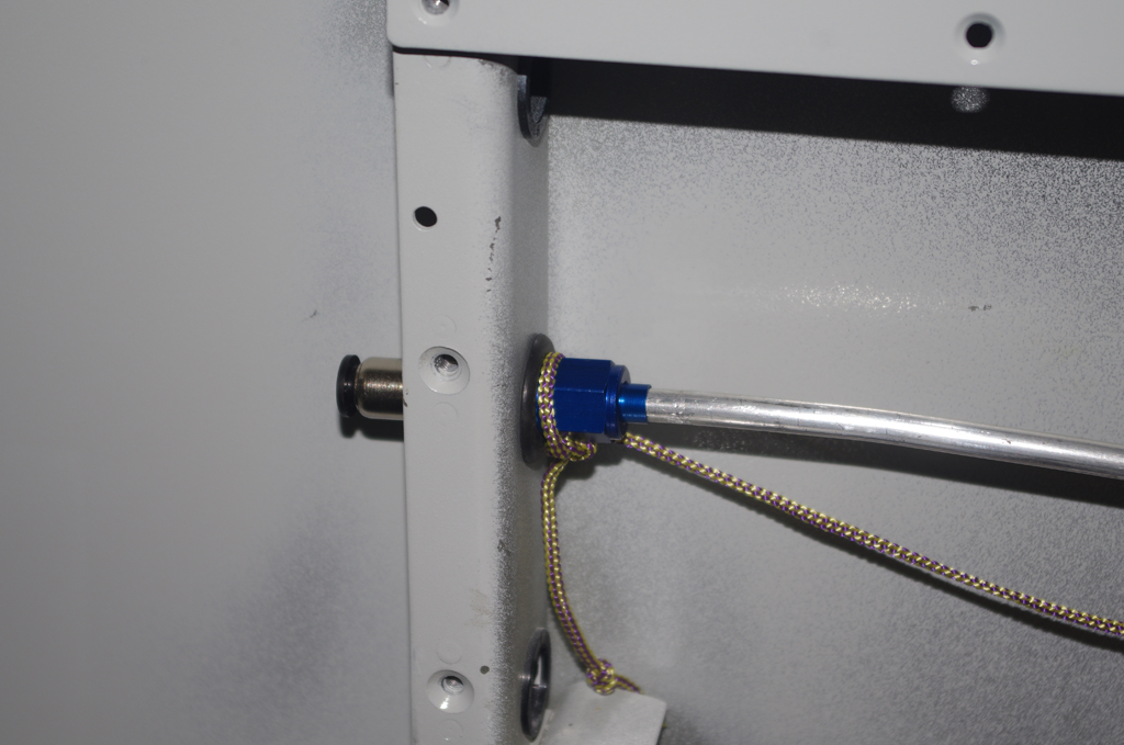
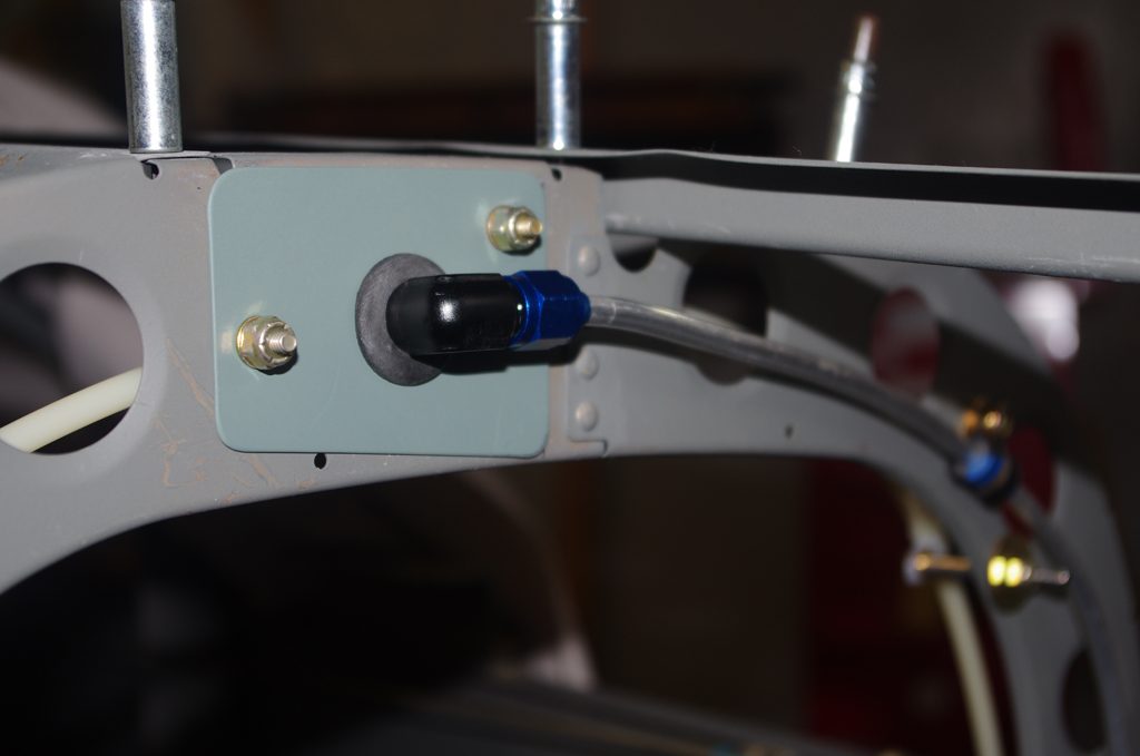
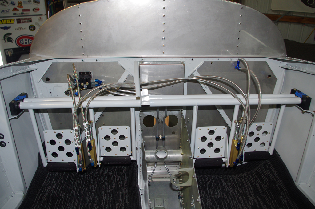
The forward and aft NACA air vents were fastened with ProSeal and #4 stainless screws into position.  Later SuperFil will be applied to smooth out the backing plate rivets.

Flap System

Next section was installing the flap levers and Pittman flap motor from Vans.

The UHMW (ultra high molecular weight) guide bearings must be relieved to fit under the kick plates in the rear footwell.  The various stages of the trimming process are depicted on the left.  The right photo was taken during match drilling AN3 bolt holes in the flap crank and torque tubes.


Proper alignment of the flap crank with the flap horns was achieved by clamping the center crank to the workbench, then using the W-730 Bellcrank Jig to establish the correct angle on the horn.  Curiously these call for AN4 bolts, while those for the flap crank are specified for AN3.


Insertion of the torque tubes was supposedly achievable from the inside the footwell, but I found pushing through the exterior access holes to be much easier.  The quick build exterior holes first needed to be relieved slightly to prevent binding on the torque tubes.


The flap motor comes without an electrical connection. The left picture shows a Molex 18-24AWG connector crimped into place.  The wires near the connector are held together with heat shrink.  The flap crank with UHMW bearing are shown on the right.


These photos show the final configuration of the flap motor to flap crank, plus a close-up of safety wire around the pivot point.  It was a slow, tricky job to drill a 1/16″ hole in the motor pushrod.  The final attachment of the flap horns will be performed after the wing root area is primed and painted.


A custom flap position sensor mount is fabricated for a Ray Allen POS-12  device.  More on this later…

Control System (1)

The recent activities were dictated by positioning new equipment in the tunnel and forward fuselage.  As a result strict adherence to the sequence outlined in the Vans plans were required, otherwise some installations out of order would be extremely difficult, if not impossible).

The elevator idler arm was deburred, primed and riveted together.  This piece is located in the tunnel between the rear seats and connects the forward elevator pushrod to the mid-fuselage pushrod.


These are photos of the control and flap system parts before fitting, drilling and deburring.  The right picture shows the aileron pushrods which link to the control stick bases.


The control stick bases were reamed for roundness after drilling the control stick itself, then were protected with tape and expandable ear plugs prior to priming the ends.  The brass bushings were then driven into the pivot holes for a snug fit.


The control column was installed with finger tight stop nuts, then the control stick bases and pushrod assembly were also loosely attached.  After adjusting the length of the pushrod assembly to ensure the control sticks were parallel, all fixtures were tightened and Torque Seal applied.


Though officially part of the rudder controls, the plastic rudder cable guides were drilled.  They were then attached to the forward tunnel.


This shows the elevator idler arm in final configuration with pushrods attached.  The space was tight for my hands when inserting the bolt, rod end bearing and washers.  A rare earth magnet on the bolt end and washer pliers greatly helped during assembly.


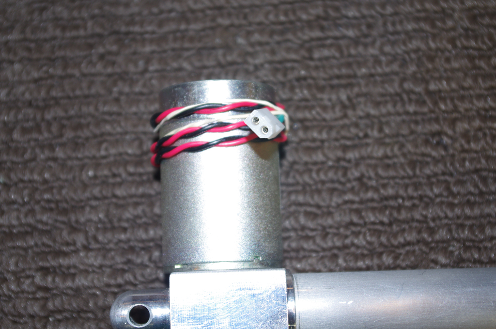
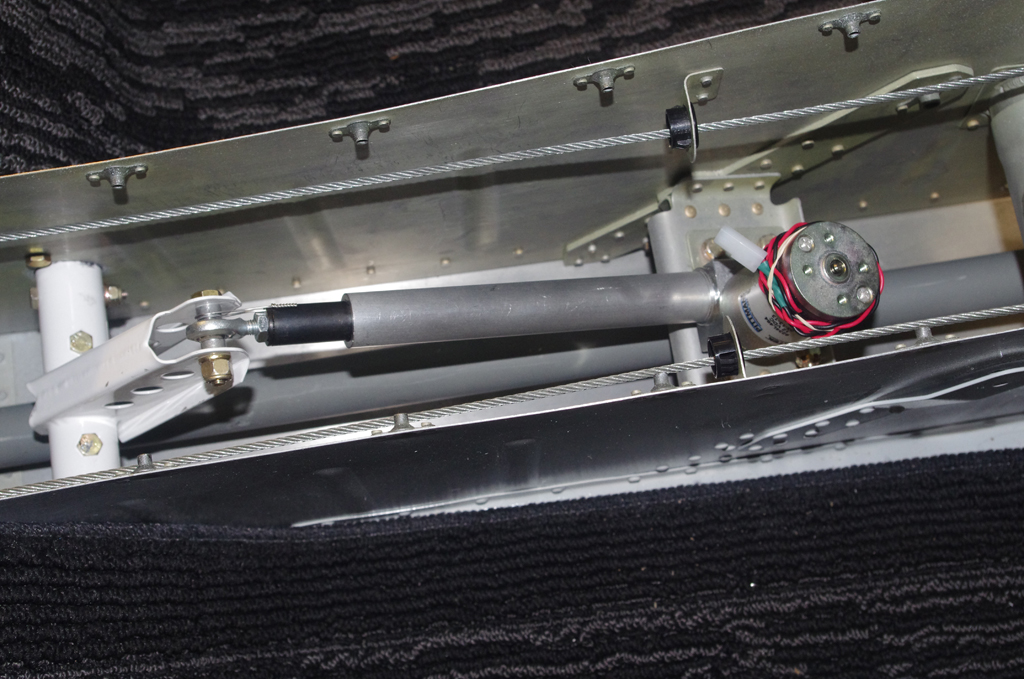
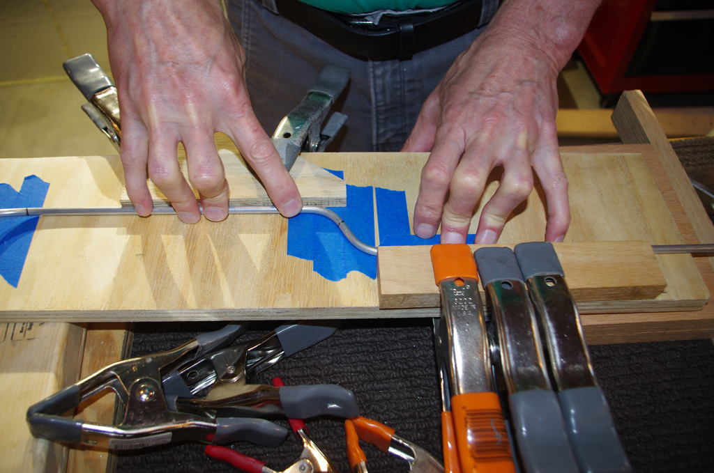
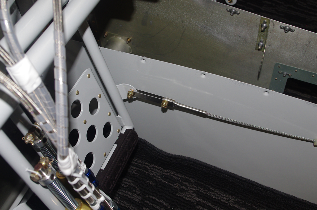
This jig was created to align the neutral position of the elevators at the bellcrank position. The final configuration was established with later posts on Empennage Attachment.


Rudder Pedals and Brake System (3)

Final connections for brake lines were completed this week.

The parking brake connected with heavy duty stainless lines to the master cylinders on the pilot’s pedals.  The Bonaco coated, flexible lines were then run through the center lever bracket to the copilot side.


Here are details about the cable lace and rescue tape applied to hold the lines in place.


MISCELLANEOUS

In researching the fuel level sensors, many recommendations were made to replace the regular gasket material with Viton.  Here are pictures of the McFarlane product to be installed at a later date. In addition, I also ordered Viton Fluoroelastomer O-rings for the #8 screws which hold the fuel sensor base plate onto the wing tanks.  These were obtained from McMaster part number 9464K12.

Rudder Pedals and Brake System (2)

Due to an interference between the original brake lines and the forward tunnel cover, I decided to a redo would be appropriate.

For this attempt at bending, a jig based on the exact firewall geometry was first emulated with coat hangers, then laid out on the workbench.  The wooden constraints matched the indented box and helped make the two 45degrees bends in quick succession align properly.


The remaining bends were rough bent with the Imperial tube bending tool. The final configurations were carefully adjusted by hand.  Since these were with the ‘hard’ aluminum, the risk of cracking or compressing during the manual operation was minimized.  I am much happier with the final outcome.


Here the forward tunnel cover was relieved about 1/2″ from the stock cutout.  Even the new, better fitting brake lines would not fit into the original space.  On the right, the pilot side flexible lines were cable laced together on the workbench.


Here the rudder pedal / brake assembly is fit into the bearing blocks and bolted to the mount plates.  The flexible lines were hand tightened to check for lines rubbing together. Pinch points will be covered with plastic spiral wrap, then final cable lacing where needed.


The left photo shows building a cardboard template for cutting ceramic mat insulation for the forward tunnel.  RV10s generate plenty of heat transfer from this location as the engine exhaust pipes are immediately on the opposite side of the firewall.  The right photo shows relieving the stock Vans fuel valve bracket to accommodate the Andair valve and TS Flightlines flexible fuel hoses.  More on both these items later.


Rudder Pedals and Brake System (1)

The continuation from the brake line fabrication is preparation of the rudder pedal system.

The bearing blocks and mount plate were laid out with the corresponding hardware ready for processing.  The blocks appear to be black Delrin (or equivalent).


The center bearing block was measured, then drilled with a #10 drill to accept AN3-22A bolts.  The block was then cut in half for later mounting to the rudder pedal brace.


The side bearing blocks were drilled about 1/8″ deep using the mount plates as a template.  The remainder of the hole was completed in the drill press to achieve perpendicular alignment.


A feature recommended by other builders for the side bearing were oil holes added to the bearing blocks. These facilitate lubricating the friction points after installation.  The depth and location are first checked before going to the drill press.


This photo shows the completed bearing blocks after addition of the oil holes. Deburring the Delrin on the inside of the bearing hole required the use of a Dremel tool.


Spacers for the lower brake cylinder attachment point were made from AT6-058×5/16 tube. These are sized to accommodate AN3-12 bolts.


The main pedal parts were staged for match drilling and preparation for priming (SEM Self-Etch Primer) and final paint (PPG Concept – Boeing Grey).


Parts staged, primed and painted.


The brake doubler plates and brake pedal side plates were riveted together to make the brake pedal subassemblies.


All the prepared parts and hardware were stage for attachment to the pedal levers.


The Vans kit uses Matco brake components.  Here the completed pedals are enhanced with AeroSport pedal extensions 3D imprinted with N190XB.  Next actions are to fit these units into the fuselage, then attach soft brake lines.

Brake Lines (2)

After bending the under seat lines, the next step was install RattleTrap xTreme sound dampening material and continue with line fabrication.

Because of the adhesive backing on the foil sound dampening (potential fire hazard), that material will only be installed under the seats and rear portion of the tunnel.  Eventually the forward tunnel and engine-side firewall will be covered with Fiberfrax ceramic mat and stainless steel foil.


Here are pictures of the brake lines installed under the left seat and tunnel.  The material used was 1/4″ diameter ‘hard’ aluminum tubing. Flexible and stainless covered Bonaco lines will be used for the pedal connections, but the idea here was permanently install the fixed lines in static locations. Hopefully they should never need to be removed.


The bends on the right line were made more complicated than needed, but this line did fit well.  The lesson learned was applied to the left side, where the construction was simplified during the bending process.


The left photo show the AirWard parking brake kit which includes a Matco hydraulic valve.  That right photo is the forward tunnel after the heater plenum was installed with #6 screws.  If in the future the brake lines ever do need replacing, having a removable plenum will make the job much easier.