Empennage Fairings (1)

After months of inactivity due to the new house move I am finally back to working on plane parts.

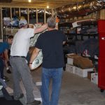
Moving day!  Here are photos for relocating many plane parts from the rented storage unit to my new basement workshop.  Outside temperatures this time of year are in the mid-90’s.  The basement has a dehumidifier with temperatures in the low-70s, humidity around 40% – perfect working conditions.


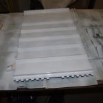
First action in the new shop was build a jig for the vertical stabilizer and bolt down to the workbenches.


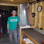
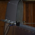
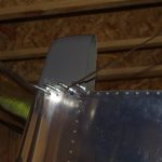
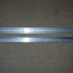
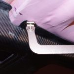
The fiberglass part needs to cover the NAV antenna holder with enough space for easy assembly. These show the initial fitting, plus the bend antenna rods in position.  Nice.


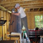
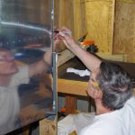
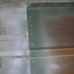
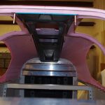
Eric helps install the rudder linkages, then rough fit to the vertical stabilizer.  This was a provisional attachment to check fit/finish. Adjustments to the flex angles and VS skins are needed.


Fiberglass caps on the rudder top and bottom are next on the TO_DO list, plus finish filling the VS cap piece.
New Home (8)

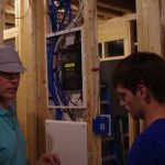
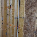
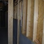
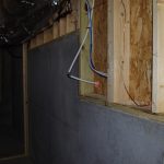
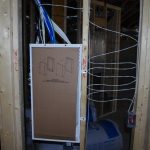
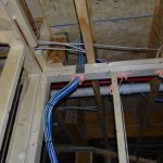
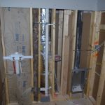
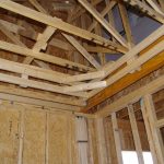
After months of packing, boxing, sanding, painting, moving… the old house is finally sold, and we closed on the new house.  This means get the electrical work done in the basement by a very skilled professional. Eight 20amp circuits were installed, should be enough to power the shop with no problems.  Next was network media closet and low voltage runs of CAT6+ cable.  About this same time Michael came to visit. Coincidentally I had lens replacement surgery in my right eye. Under doctors instruction I was not allowed to do anything for a few weeks.
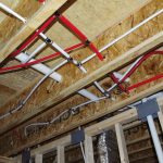
 

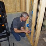
Michael did the majority of the low-voltage work.  These photos show him terminating ethernet cables at the media closet and in the field.


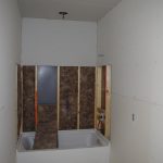
Not quite finished, but way better than the mess left by the builder.


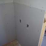
Plastic serves as a temporary wall between the shop area and the office.  I may consider later this year I putting up drywall and finishing the right side of the basement. Back to plane building first!


New Home (6)

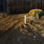
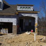
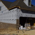
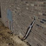
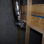
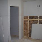
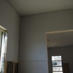
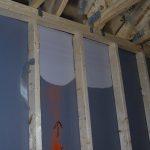
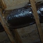
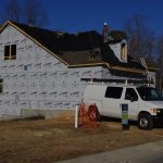
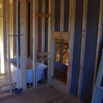
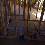
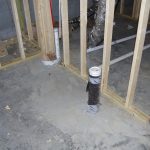
Not much happened over the Christmas holidays, but plenty of action since the New Year.  Biggest item is a second HVAC unit for the second floor and revamped ducting in the basement to allow 9′ ceiling in most locations.  Not optimal, but way better than before.  They also finished the back deck, insulated around exterior walls, and mostly completed drywall rough-ins.  Current schedule is house completion in early April.


Rear Seat Backs

The work on these seat backs seems simple compared to some recent activities, but nevertheless takes time to do right.

Typically I cut the parts, debur and scotchbrite, then layout before further processing.


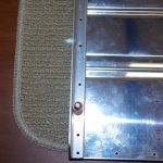
Fastening holes are measured on the rear seat back corrugated material, then #30 match drilled with angle brackets.


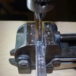
Upper and lower angles are measured and #30 holes fabricated with the drill press. These become the template for holes in the corrugated material.


The upper angles needed to be rounded on the inside for a tight, nesting fit with the rear seat back.  The bench sander and scotchbrite wheel were used to provide the relief. After dimpling and countersinking as specified the areas joined together are self-etch primed.


The alligator-jaw pneumatic squeezer is used to rivet the parts together.


The almost finished seat backs are test fit for lower hinge alignment, then riveted together.  Last step is a light coat of sandable primer. Eventually they will be painted the same Boeing 707 grey as the rest of the interior.

Overhead Console (1)

The Christmas vacation provided opportunity for some significant shop time.  The main focus for the 10 days off was fitting the overhead console and fabricating the rear seat backs.

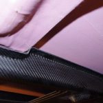
The carbon fiber console was obtained from AeroSport Products. It is very light weight, but not exactly proportioned to the Van’s cabin cover.


The middle portion needs to be relieved to accommodate the heavy fiberglass reinforcement section of the cabin cover.  This element apparently is very significant to the structural integrity of the plane and everyone suggests no alterations to this element should be undertaken.  My intention is feather the console into the ceiling with fiberglass and paint (no need for the carbon fiber look).


Here are photos of aligning the rear console with the baggage bulkhead.


A #30 drill with a drill stop set to a depth of about 1/4″ was used to drill through the carbon fiber and the under layer of fiberglass/resin of the cabin cover – just enough for a cleco to grab. Drilling much further would penetrate the outer fiberglass, definitely not recommended.


The console was removed and modified for the center bracket, then refit to check clearance.


Here the console is shown in final fit configuration.  Further work on vents, lights and cabling will be performed with the cabin off the plane.  With the canopy upside-down gravity will assist holding the console in-place.


New Home (5)

Electrical and HVAC installations continued over the weekend.


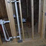
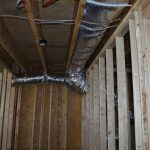
Notice on these next pictures how the engineered floor joists have been completely cut through the web to accommodate the AC ducting.  I do not think this is correct and will be taking up the matter with both the builder and the city inspector’s office.


Cabin Cover (5)

This week was about finishing the rear windows and starting on the windscreen.

The  process for the rear windows is about first getting close to the scribe line with a Dremel tool. Then using 120 grit sanding belt before hand shaving closer with 220 and polishing/rounding the edges with 320 grit.


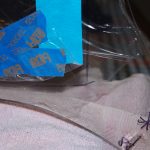
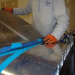
For the windscreen first peel back the protective covering just enough to expose the previously marked scribe line.


The windscreen is a slightly different process, as it is much thicker (roughly 1/4″ Lexan or acrylic).  My technical counselor advised against using a Dremel tool, saw or other cutting mechanisms (tend to cause cracking in this type/thickness material).  Instead a 3″ belt sander with 80 grit paper is used to get close. Everything else is by hand.


When talking about ‘by hand’, I mean hours of edge sanding with 80 grit paper on a Great Planes sanding block. Going through Lexan this thick takes time. Check for fit, mark the high spots, and repeat over, and over, and over…


The hand shaping process requires many iterations, but this way has less danger of removing too much, too fast in the wrong places as with power tools.  The final outcome is coming into shape nicely.  More of the same fitting process this weekend before the edge polishing can begin.

New Home (4)

Updates from December 9 week.


Cabin Cover (4)

Attaching the center console brace and beginning to trim window panes was the order for the day.

imgp7261The center brace is clamped in the middle of the forward canopy cover, then match drilled with a #12 drill to accommodate an AN3 bolt.  This is tightened down to fasten the brace, so the the rest of the holes can be drilled.


imgp7263Here is how the top of the outer cabin cover looks after the fastener holes are completed.


Here are left/right pictures of the bottom portion of the center brace attached near the firewall.  Two AN3 bolt hole are drilled between an angle bulkhead and a reinforcing plate.


imgp7274A set of spacers 1-13/32″ long  are fabricated from 5/16″ diameter tube.  This will eventually be driven into enlarged holes for the center brace.  The cabin cover needs to come off for further processing, so this step will be saved for later.


imgp7265The plans call for fitting the windscreen first, but I wanted some experience dealing with Lexan/acrylic trimming beforehand.  The side windows will be my test platform – if things go south these will be cheaper and easier to replace compared to the windscreen.


imgp7275imgp7276Pull back the protective covering and get ready to power trim!

Cabin Cover (3)

Over the Thanksgiving week off the focus was finishing major elements of the cabin cover.

imgp7192The first step was complete match drilling the mid-skins to the cabin cover.


imgp7191imgp7194Next was clamp the rear door frames to the bulkheads and match drill for #10 countersunk screws.


imgp7200imgp7198Here the right side has been drilled and clecoed into place.


imgp7206Now for the forward door frames. The gusset  is clecoed to the bulkhead, but match drilling for the #10 screws to the fiberglass frame goes through about 1/4″ of empty space. According to the plans, this space will have structural filler applied.


imgp7226

imgp7225Getting the fiberglass trimmed for the front deck took quite some time. (between initial Dremel tool sanding and hand filing).


imgp7211imgp7216Next was measure the door jam bottom, then drill #19 holes for #8 countersunk screws.


imgp7254imgp7257Check for size, then countersink with an angle tool.


imgp7258The final product looks pretty good.


imgp7221imgp7220Now rough fit the center console brace.  Overall starting to look like an airplane.