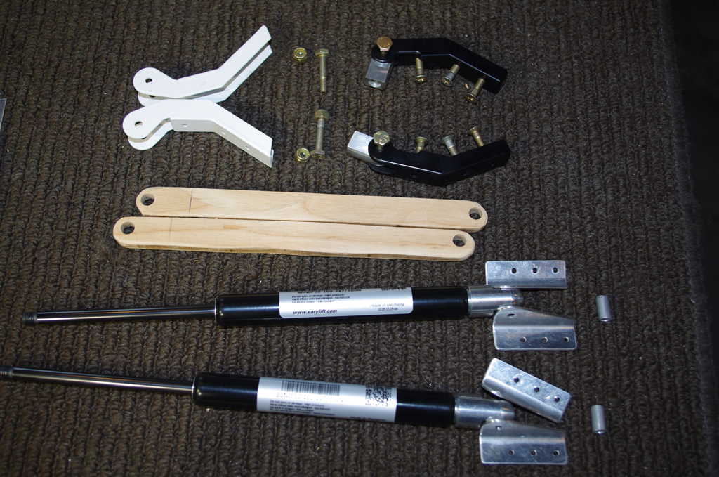
Over the past few weeks, many distractions for home improvements have gotten in the way of progress on the plane. However, a recent visit from Rich has helped put wind back in the sails. My approach was to finish as much work on the latches, gear boxes, pin blocks and other accessories prior to bonding the inner and outer shells together. Made for much easier access to some tight areas.
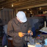
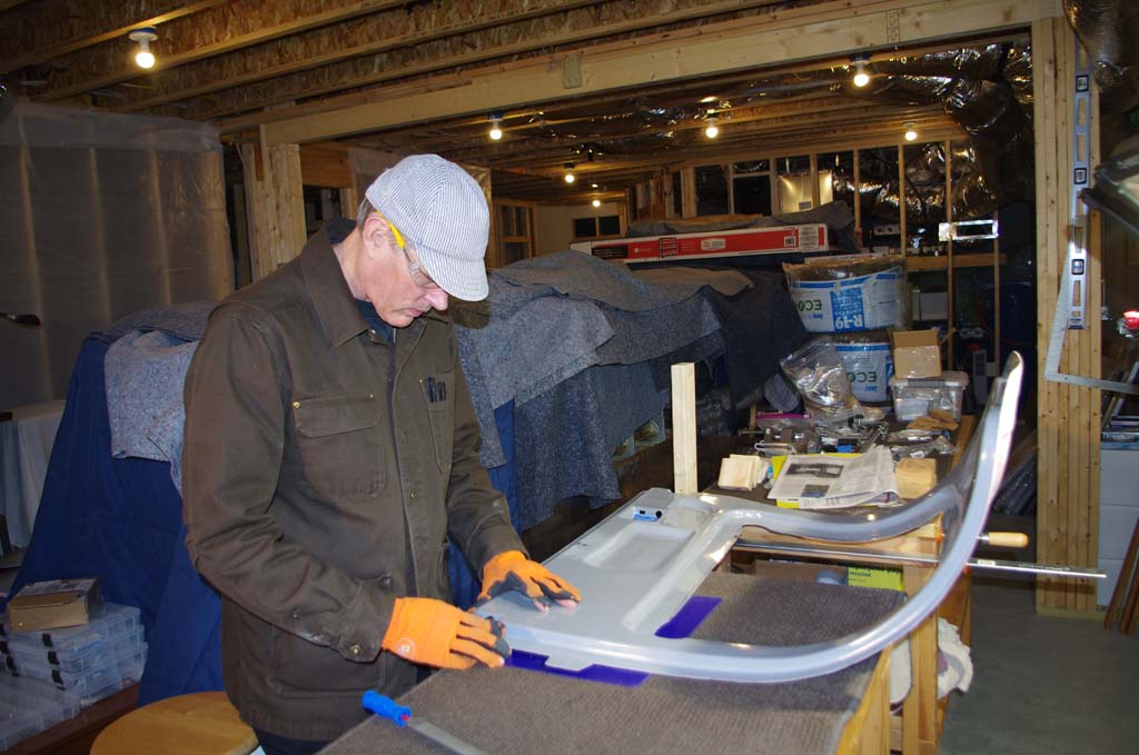
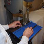
 Here the Delrin pin blocks from PlaneAround are being shaped with a vixen file to match the corresponding door pockets.
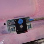
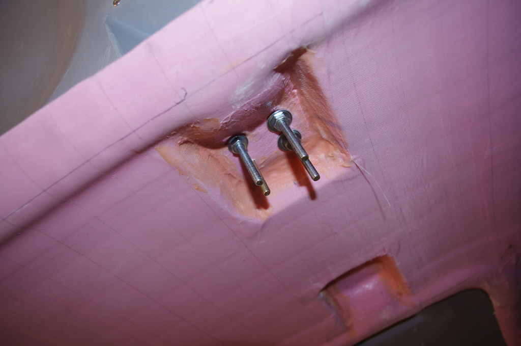
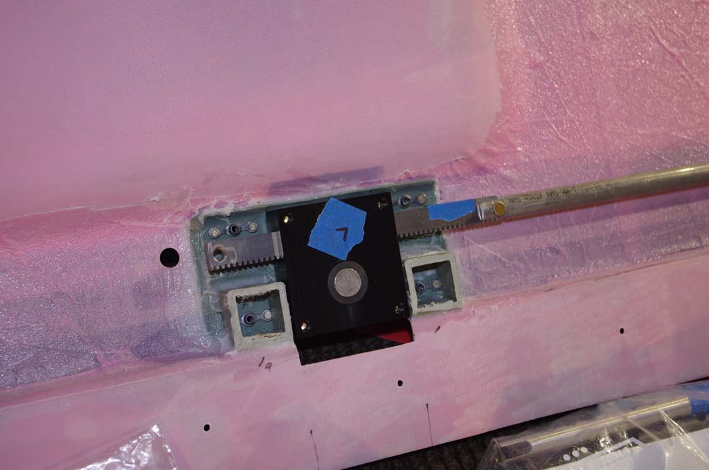
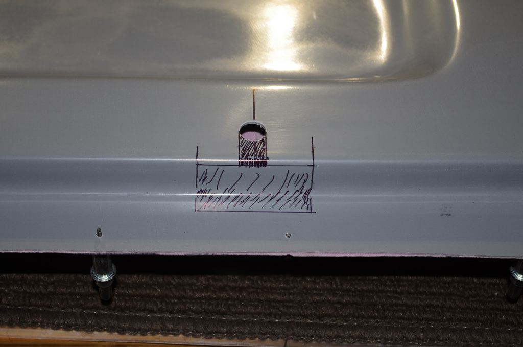
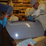
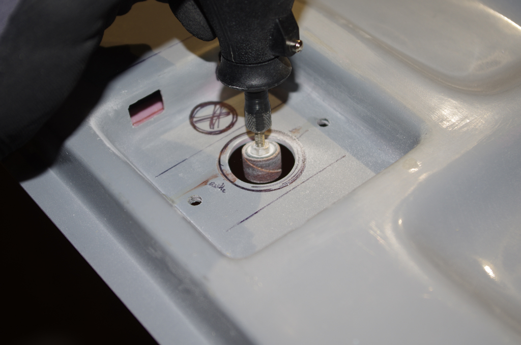
 Next action is bond on fiberglass reinforcement squares from the PlaneAround kit around the center gear box. A cover plate was fabricated to cover the cam shaft slot opening on the inner door panel. This is not required for structural reasons, but should add a finished look.


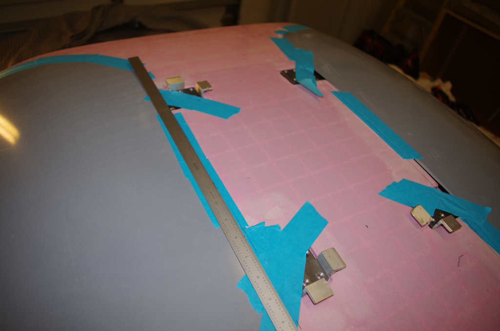
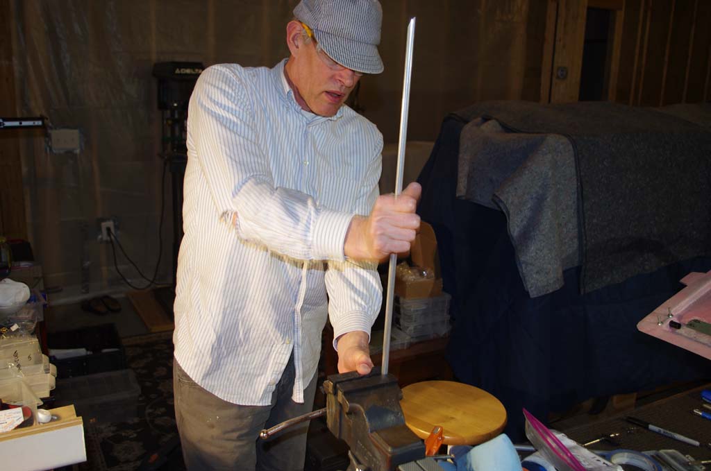
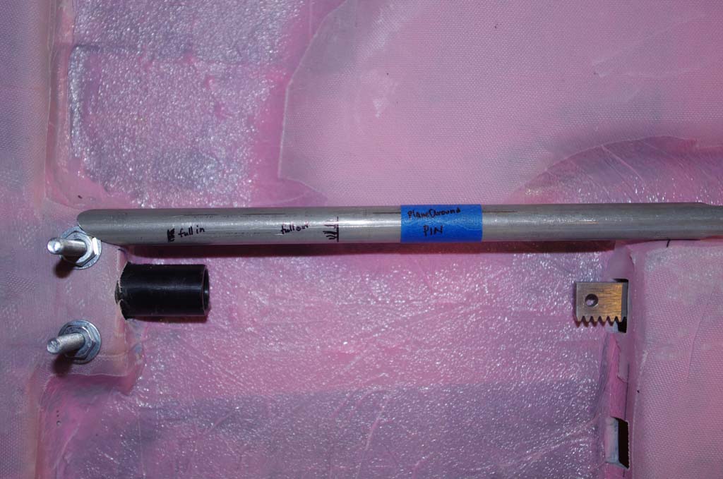
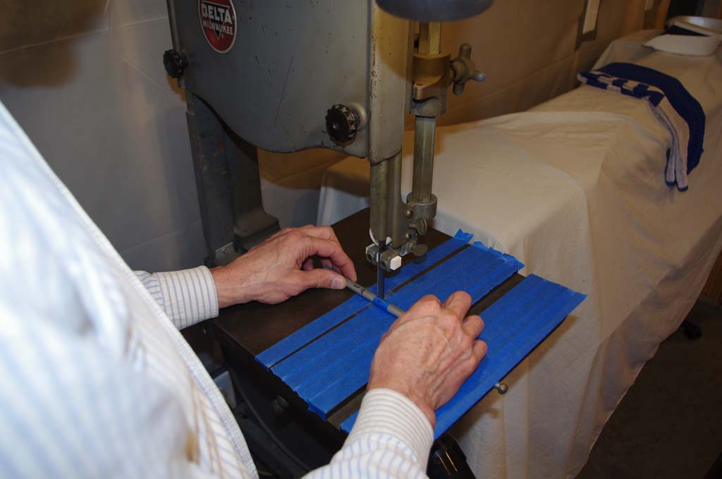
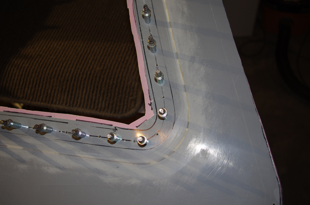
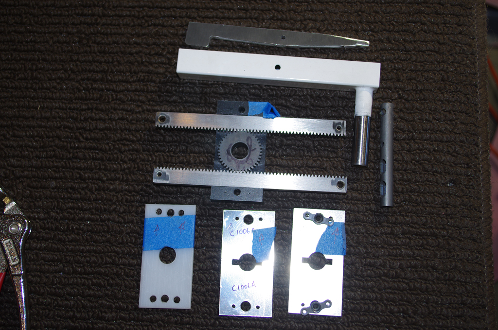
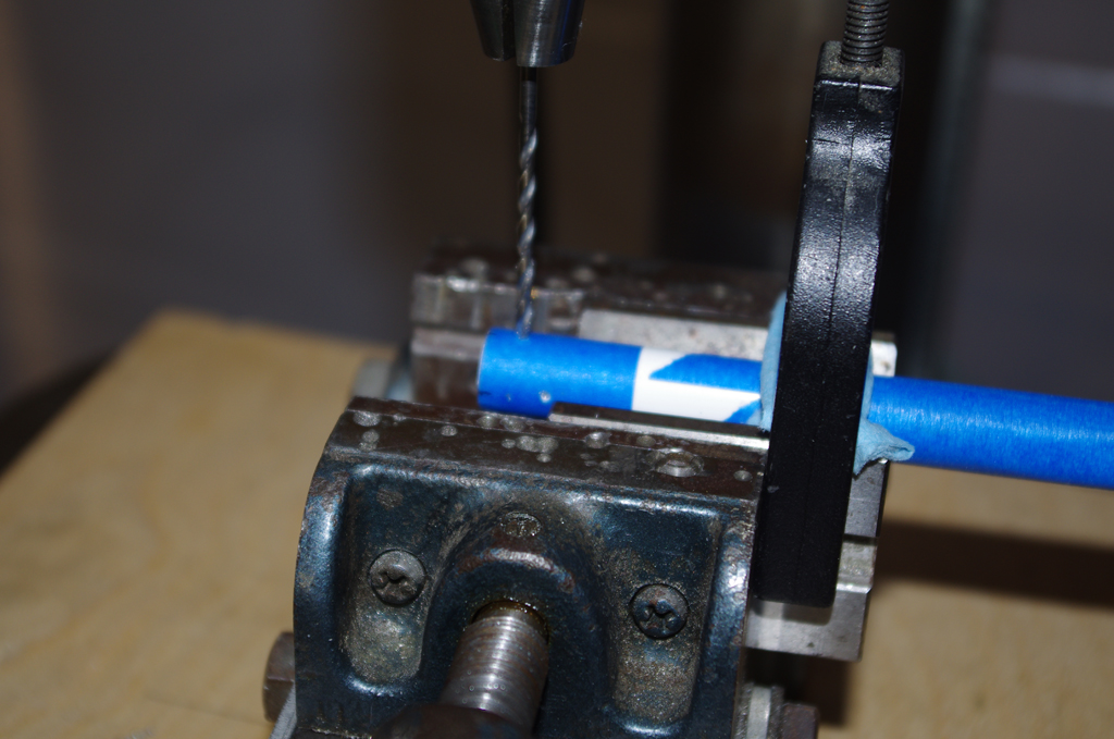
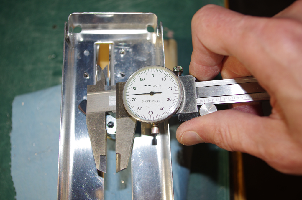
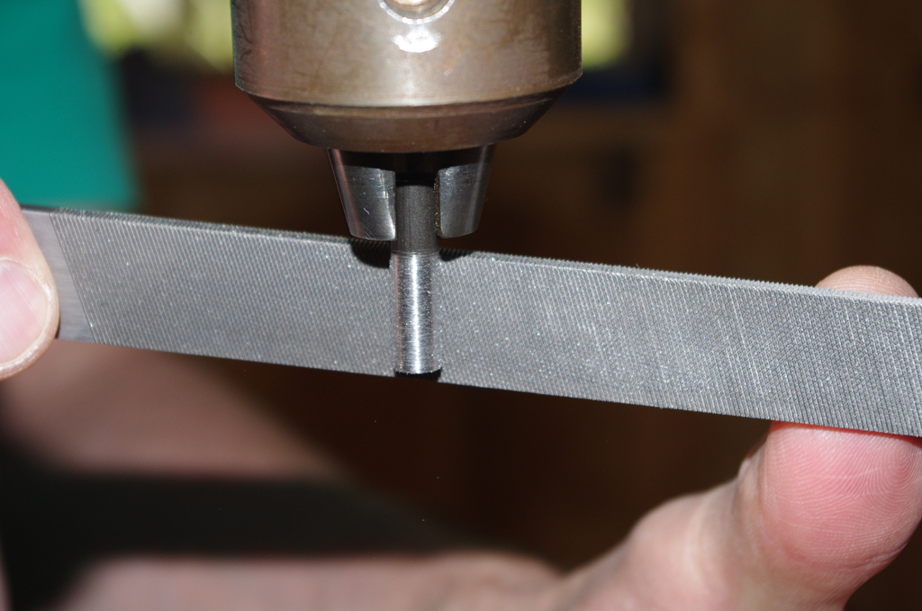
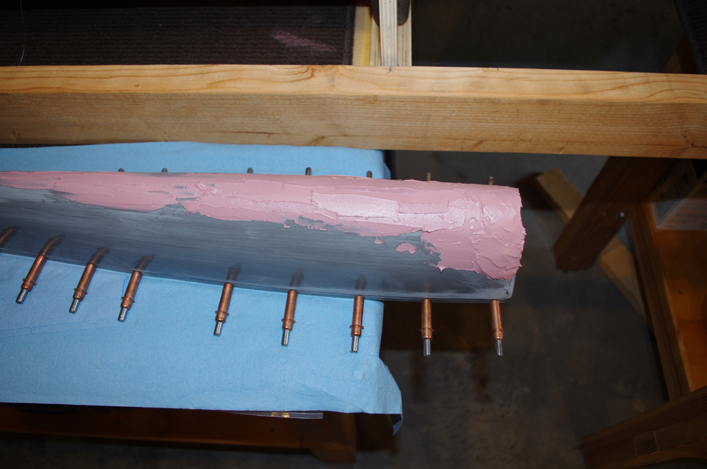
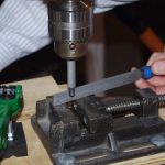
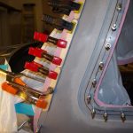
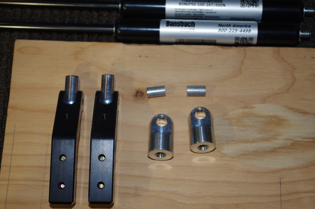
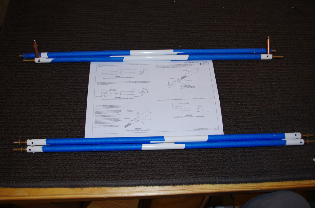
 The default Van’s pins are bent, measured and cut in preparation for adding stainless steel and machined PlaneAround pin tips.
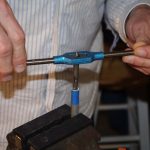
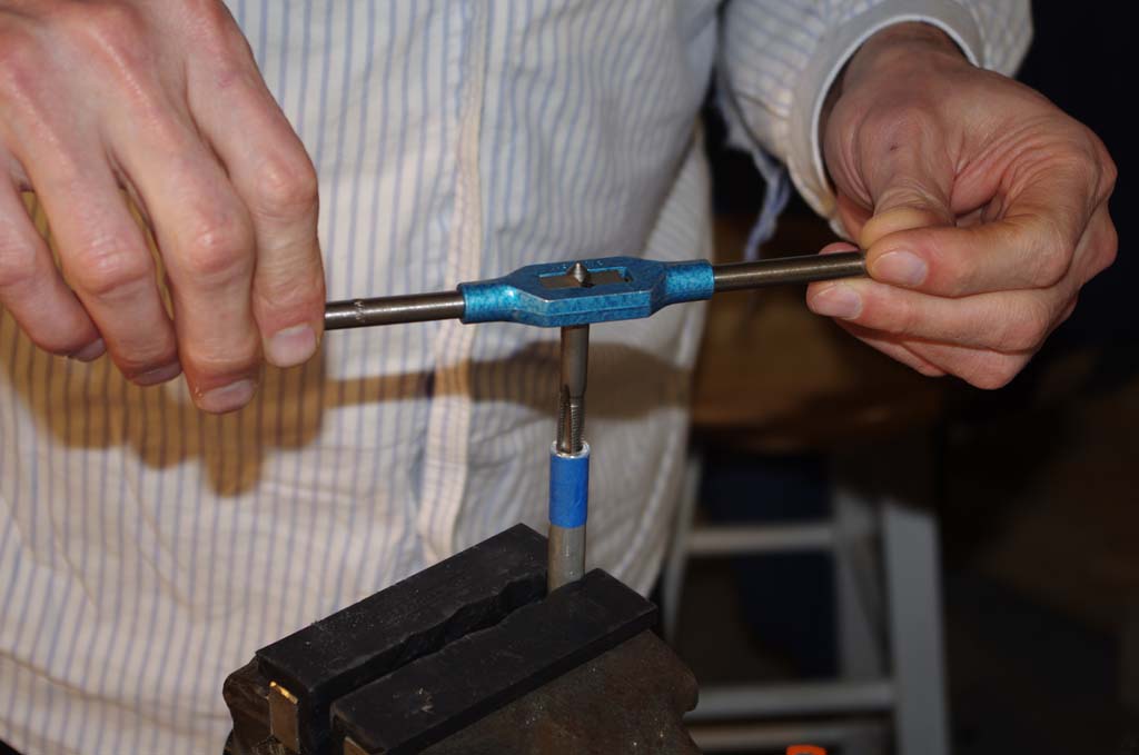
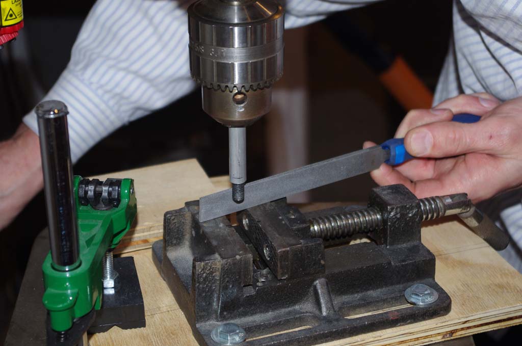
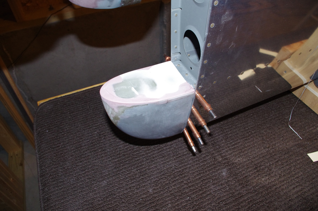
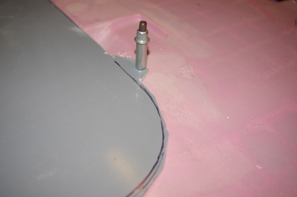
 The pins are cut to approximate length, but must be hand filed for the machined pin face to be oriented correctly. When done right, the pins should pull the door down and in when engaged. The pin is tapped for a 3/8-24 bolt which is tapered slightly for easy insertion.

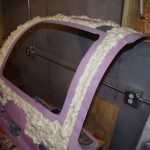
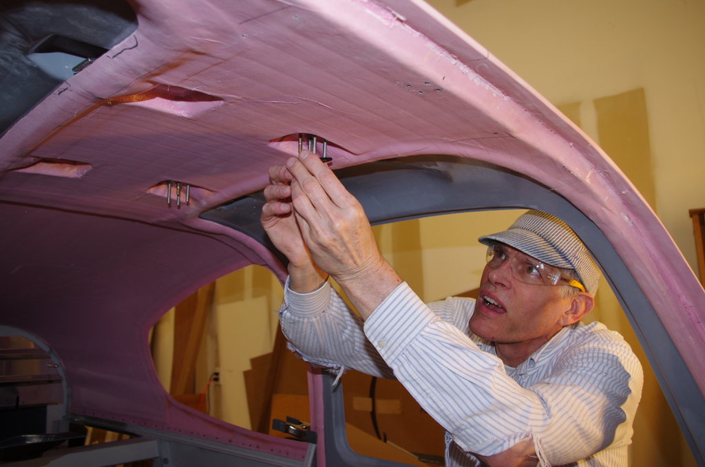
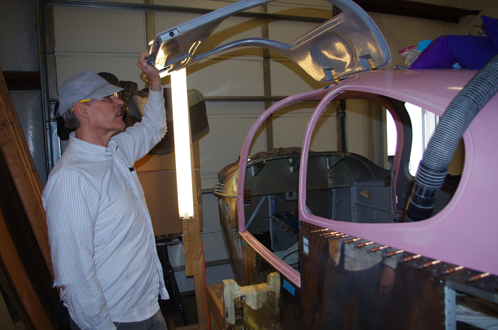
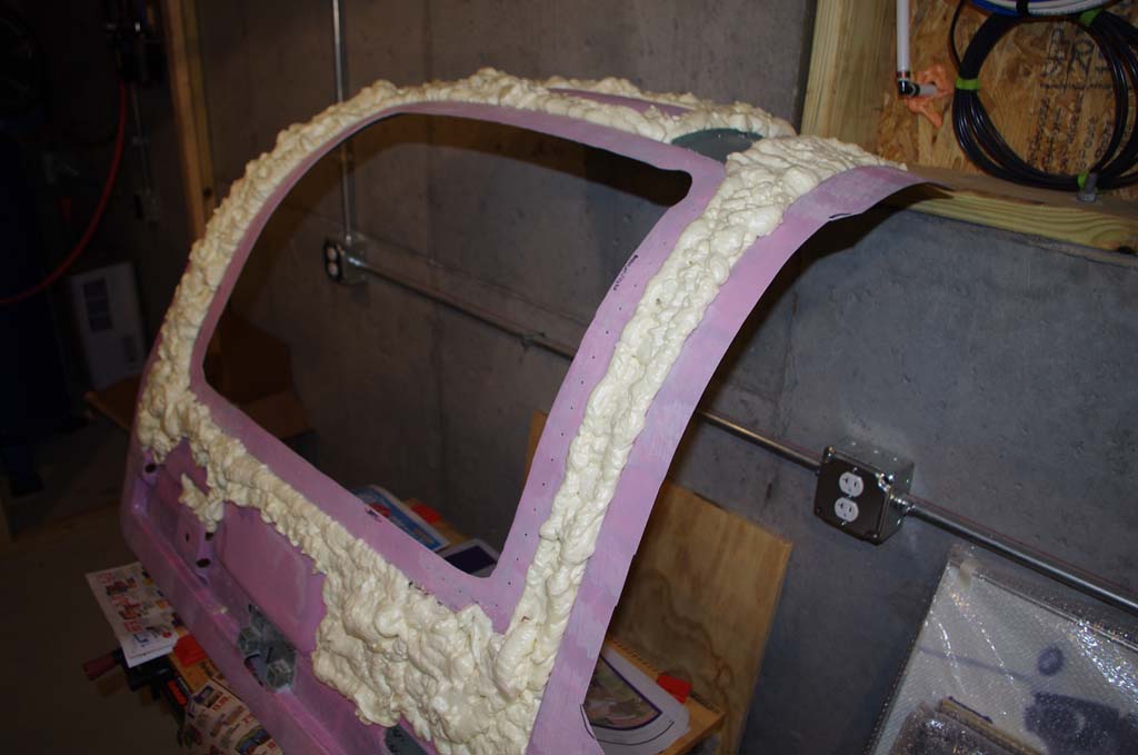
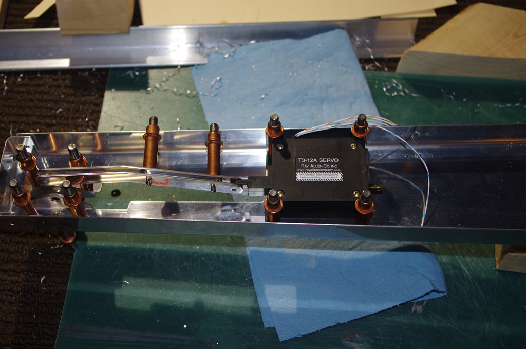
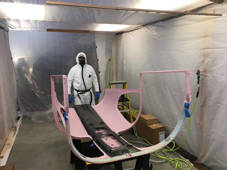
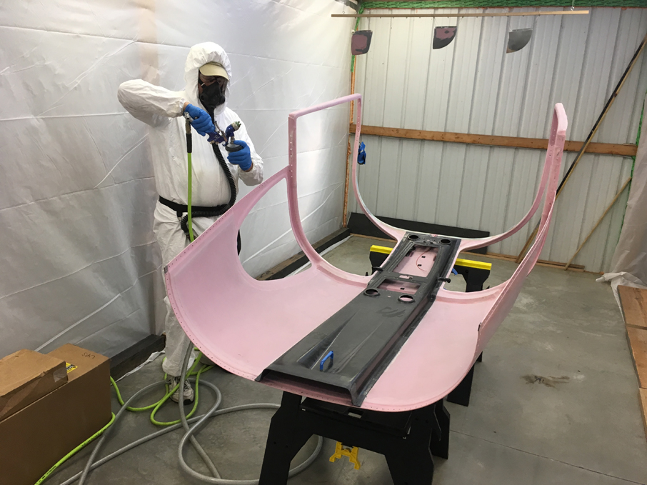
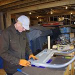
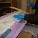
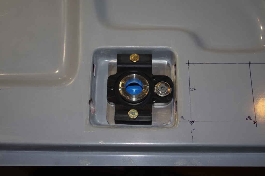
Rich confirmed proper geometries and alignment of the latch parts, then began preparing to apply foam for sound dampening.
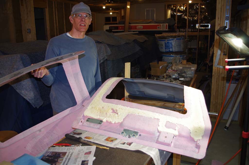
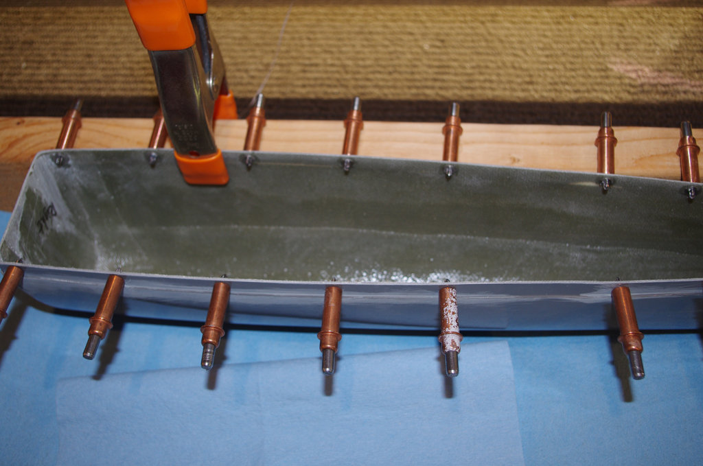
 The last step before bonding is shave the foam flush with the inner surface. The shells edges were sanded and test fit to ensure no excess foam interfered with smooth surface contact.
BONDING PROCESS (over a few days duration) ================
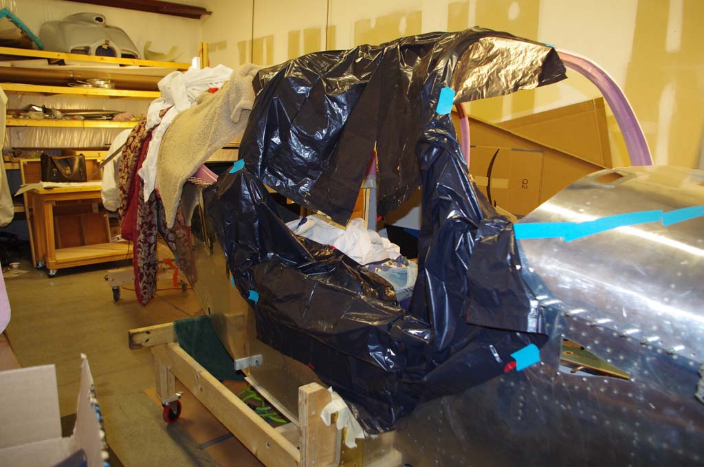
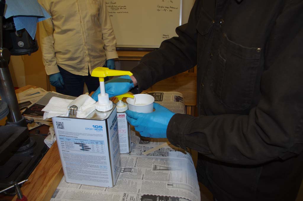
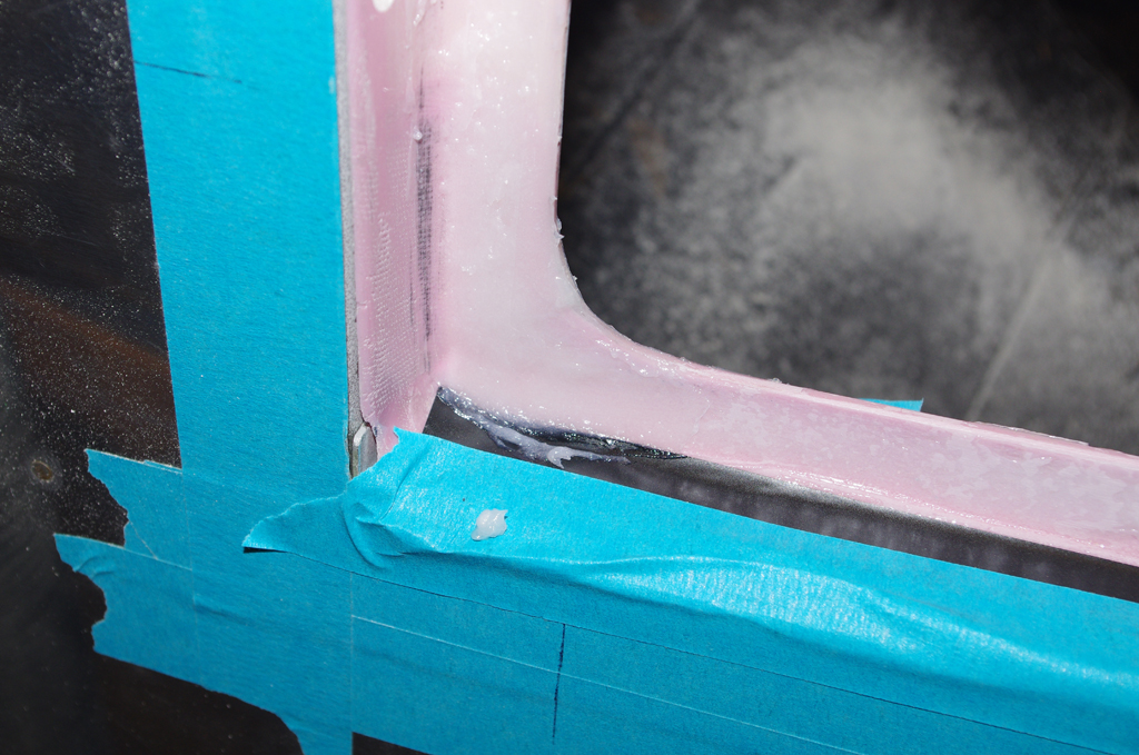
 Over at the rented shop, the right side is covered with plastic to prevent extra adhesive from squeezing out the edges onto the canopy. Then West System epoxy is mixed together. A batch of ‘neat’ (no fillers) with three pumps resin and three pumps hardener was prepared to wet both shell surfaces.

 Here the elbow pocket is covered wet before application of a 5 x 9 inch piece of Permabond (triple layer fiberglass mat). The mat was thoroughly soaked in neat adhesive.
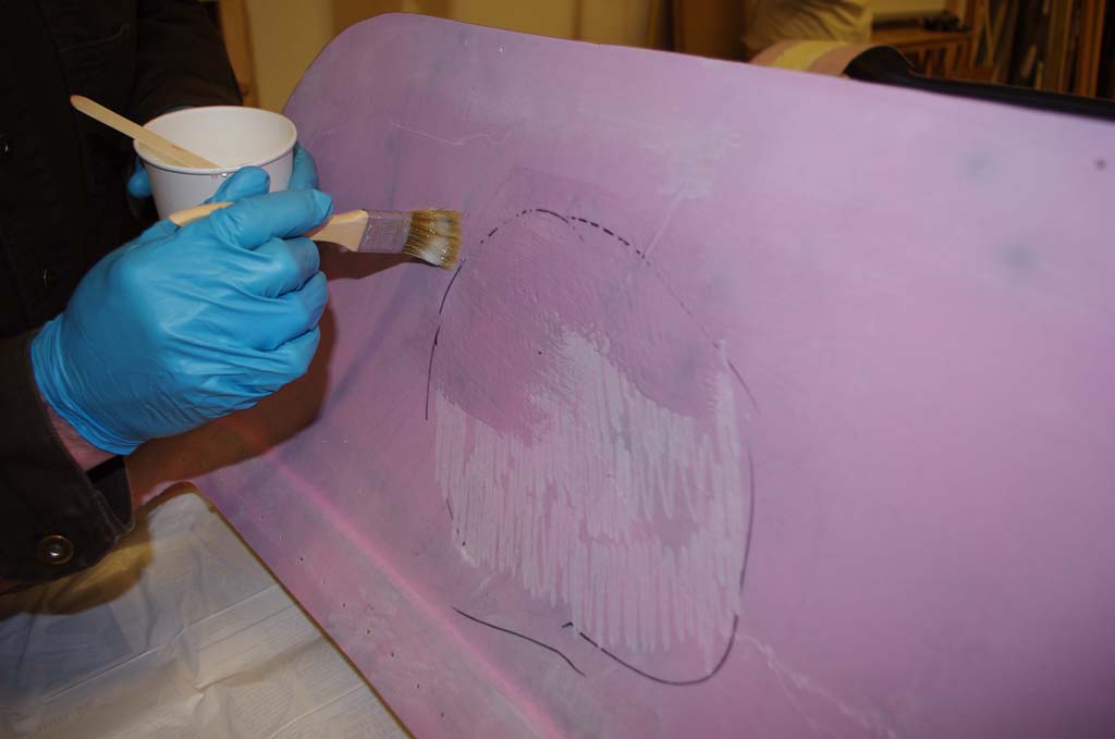
 This photo shows wetting the cranial cavity on the inner shell. This area was treated with the same Permabond as for the elbow pocket. After this operation, I had an issue with the bonding material used for the right door outer edges (more on that later)…

 When done properly bonding the outer edge used three separate batches of three pumps each of resin/adhesive first mixed together, then stiffened with six spoonfuls of West 406 (colloidal silica). The consistency turned out similar to peanut butter. The final adhesive mixture was spread about 1/16″ evenly on each surface before mating together.

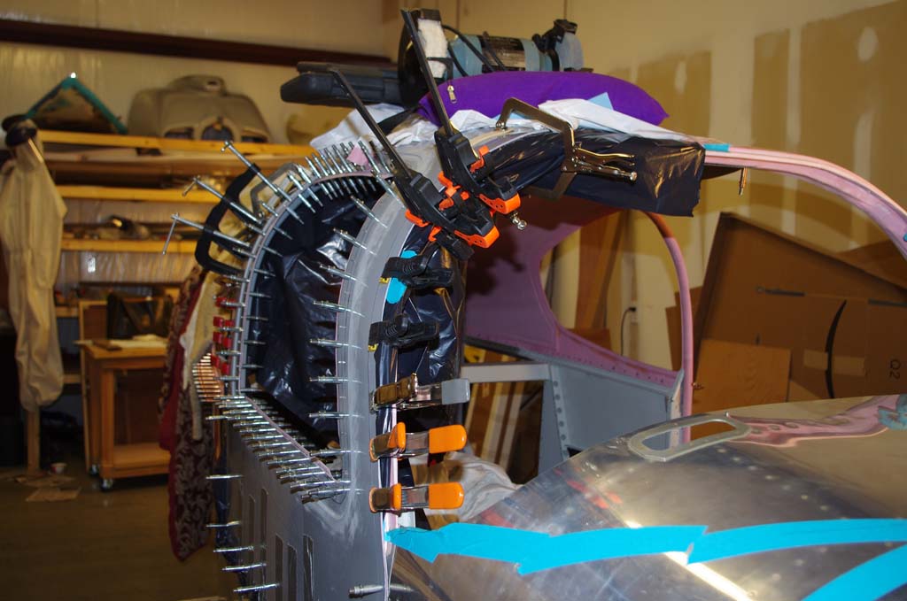
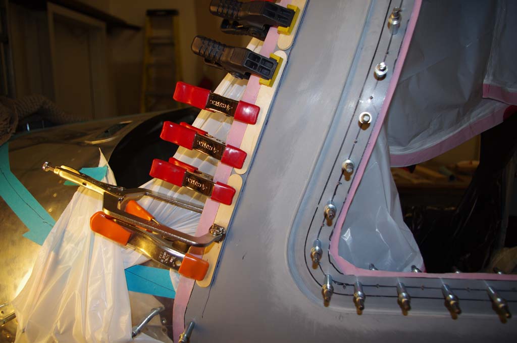
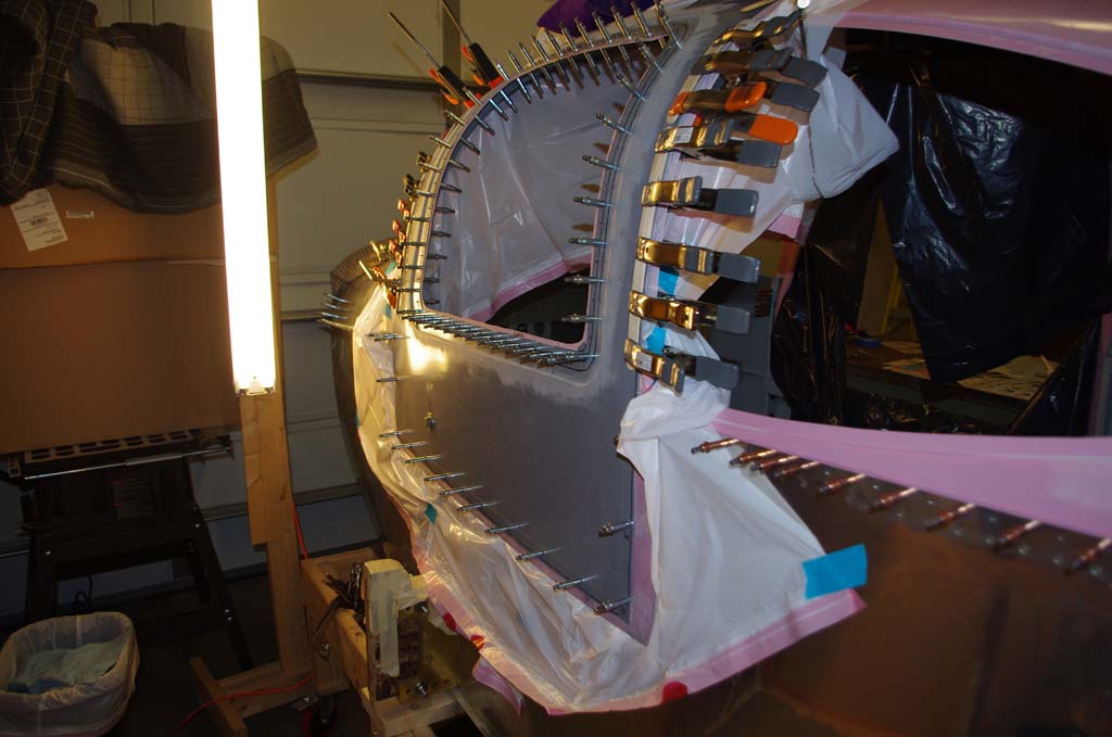
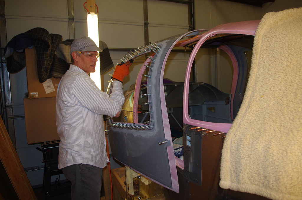
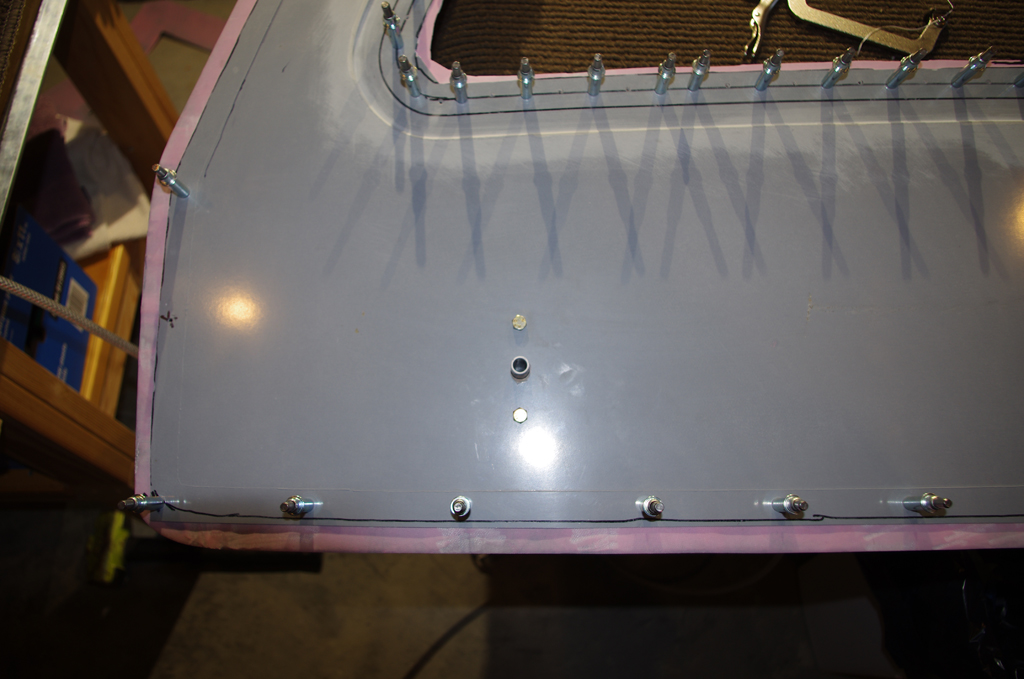
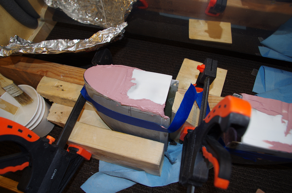
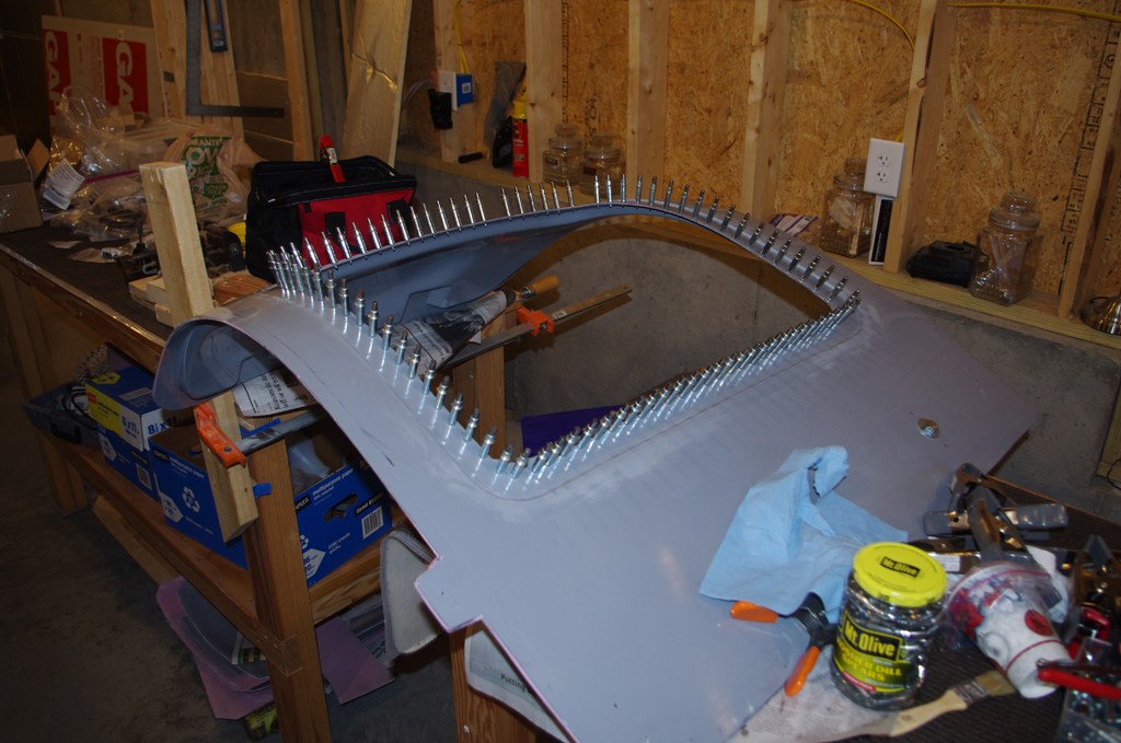
 Clecoes hold the lower section to the fuselage through witness holes. Clamps have been applied to the sides along the door channels. Sandbags about 25 pounds each and other extra weights hold the top section in place.
 Rich had the good idea of using kraft sticks to distribute the clamping pressure along the door edges. A firm, uniform clamping force is desired. Too much pressure causes the adhesive to be forcefully ejected from the bonding location – effectively ‘starving’ the joint and causing a weaker bond.
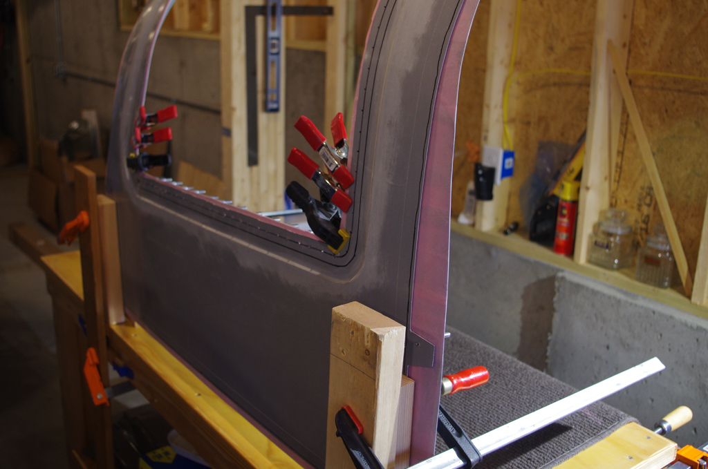
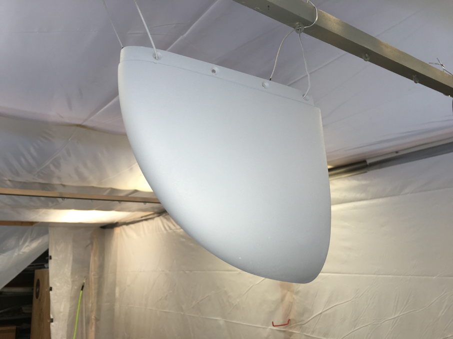
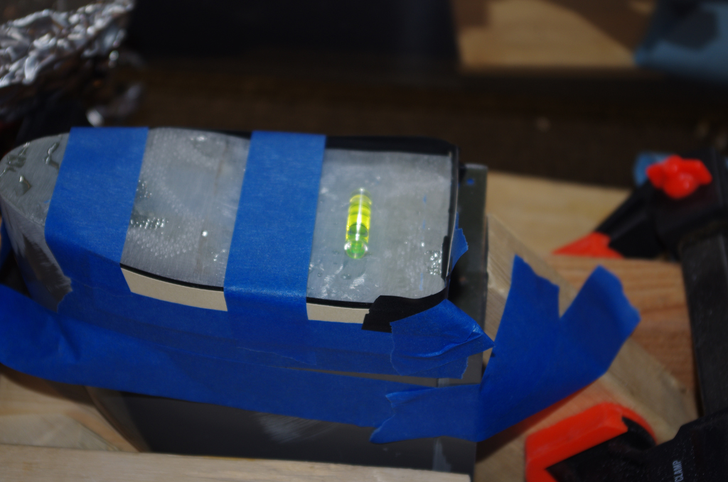
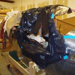
 Here is photo from a different day of the left door clamped onto the canopy to cure. The recommendation is allow 24 to 48 hours to harden before removing. This lets the door permanently shape to the contour of the canopy.
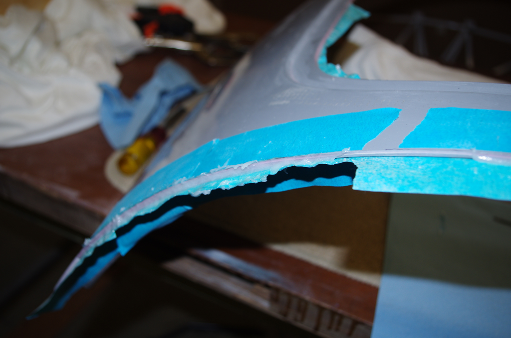
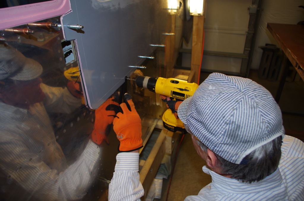
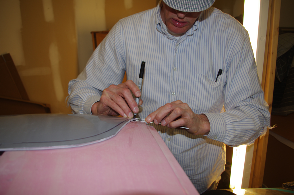
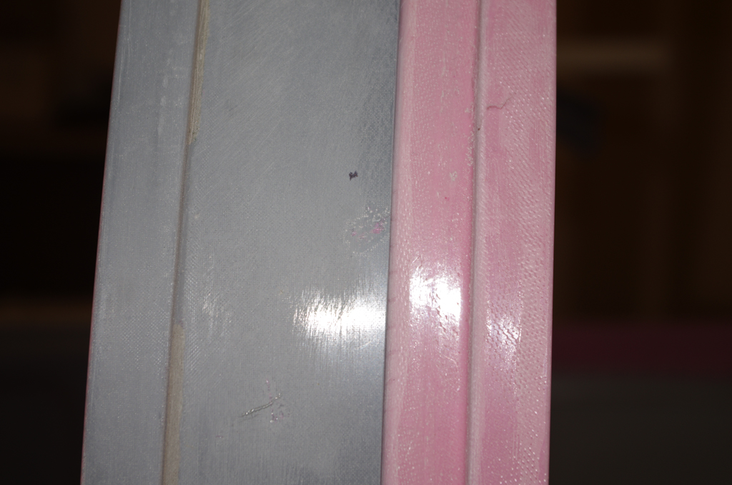
 The bonded door shells are very tight, no fear of delamination here! Now begins the process of trimming the shells to final dimensions. First the window frames, then the door edges to match the frame openings.
Confession time: On the right door I mistakenly used sealant instead of fiberglass adhesive on the outer edges. Fortunately I was able to completely remove the sealant before proper application of the epoxy adhesive. Overall the final outcome for both doors was very good and structural integrity is preserved.
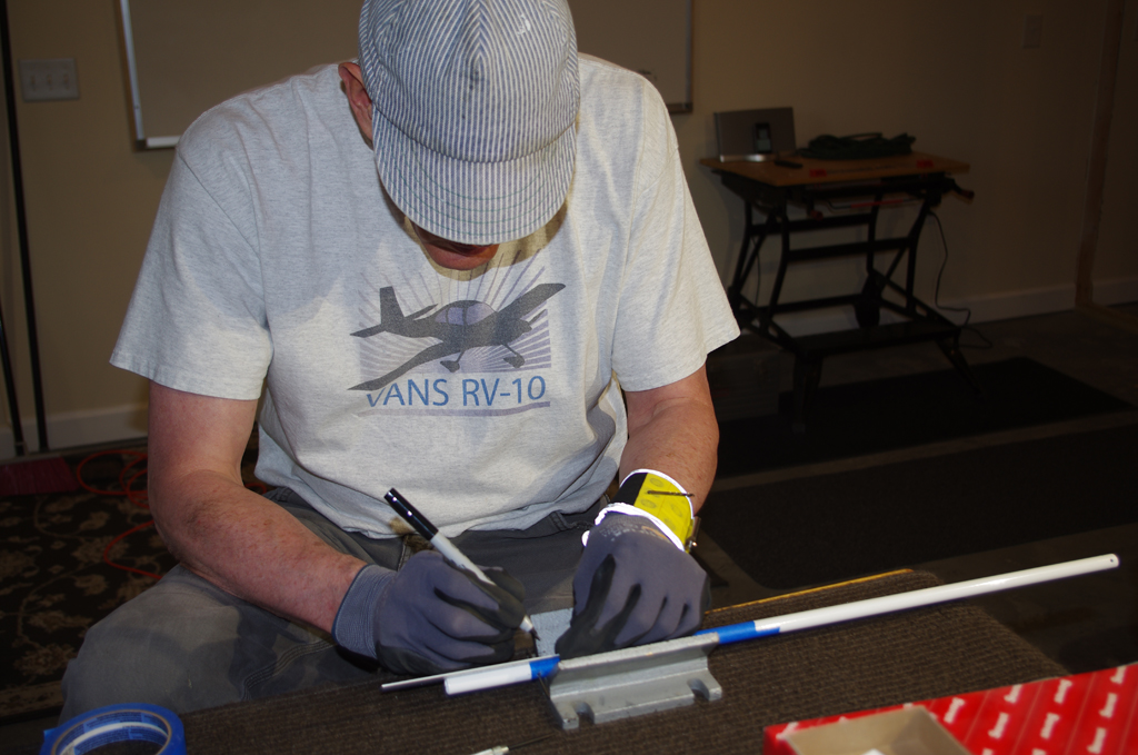
 First steps are layout the pin guides on a sheet of .040″ aluminum. The designated 6.8degree angle supposedly compensates for the angled door frames. A protractor is used to get the angle close (only has degree increments).
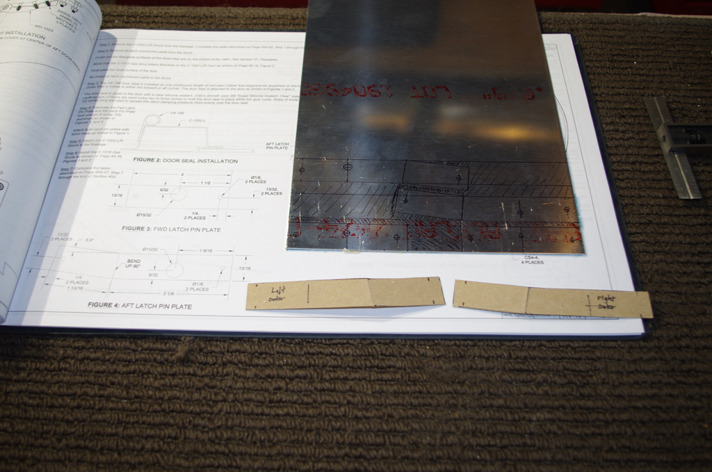 Stiff construction paper prototypes were cut prior to making any metal parts. I wanted to check the effect of the angles on the corners. Close enough for some hand shaping to be effective.
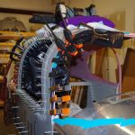
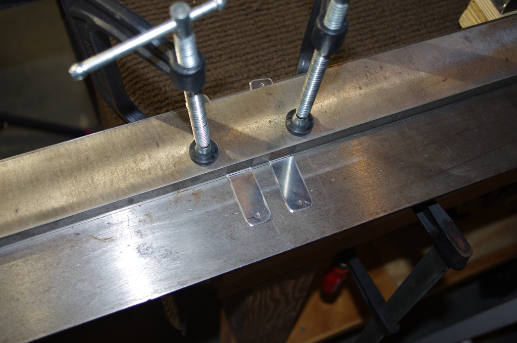 The roughed out pin guides are then inserted in Tal’s sheet metal bender and formed per plan instructions.
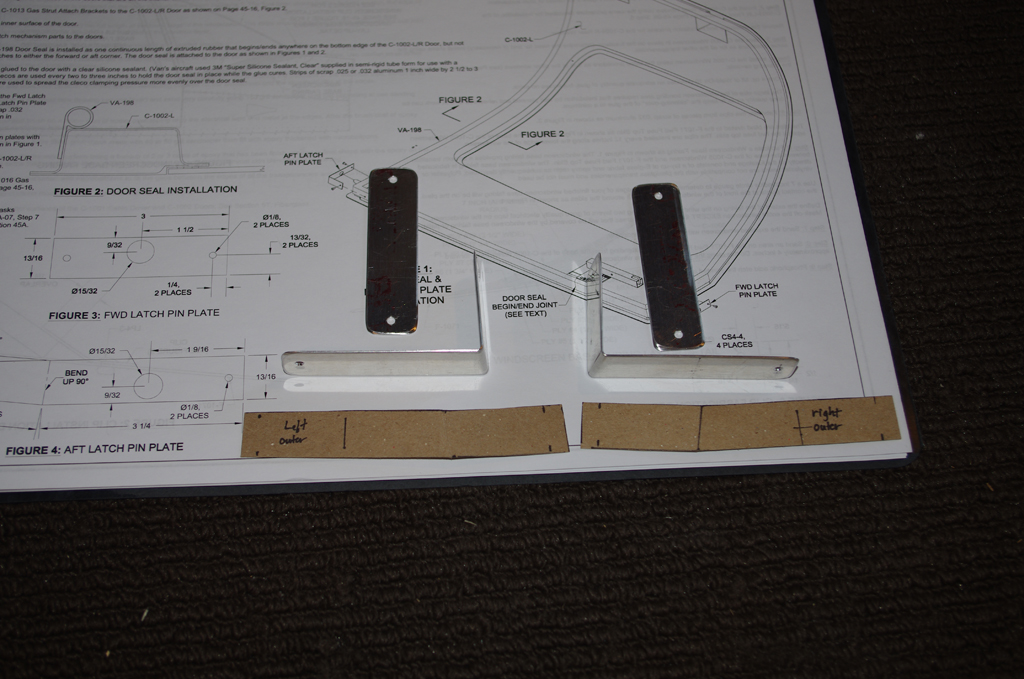 Here are the pin guides prior to fitting on the doors. Actual fitting required a bit of material removal. In retrospect I would first fit the pin guide hole from a slightly larger blank template, then shape down the attachment tabs to fit to the door geometry.
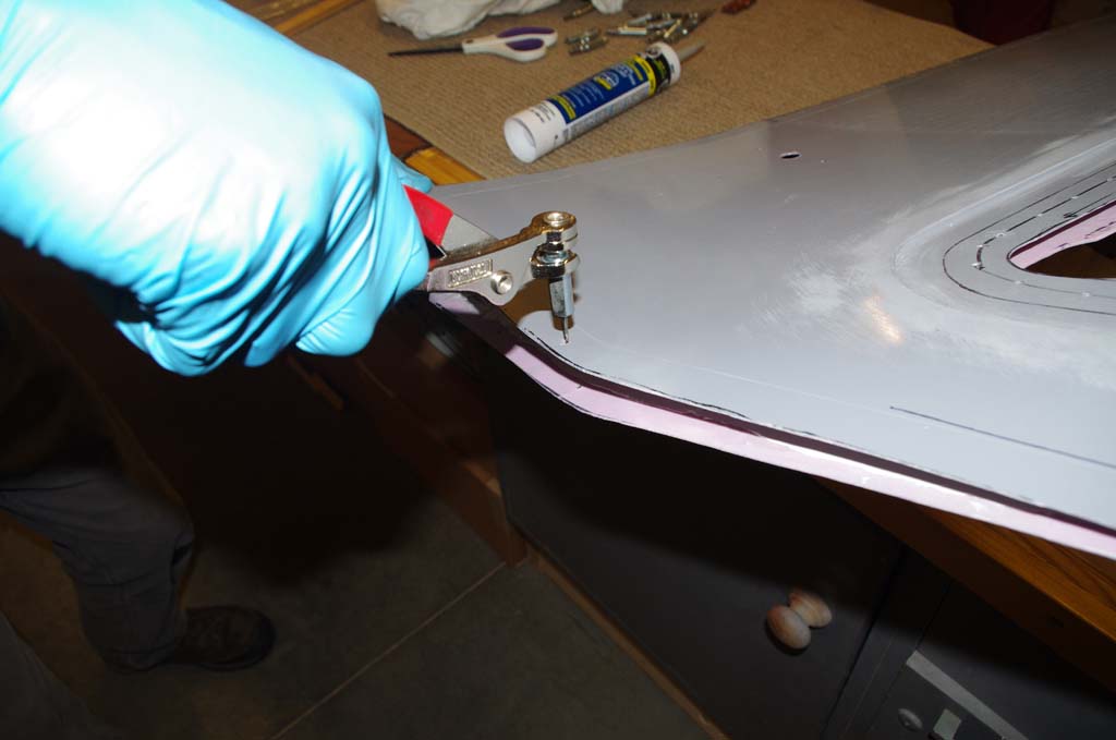
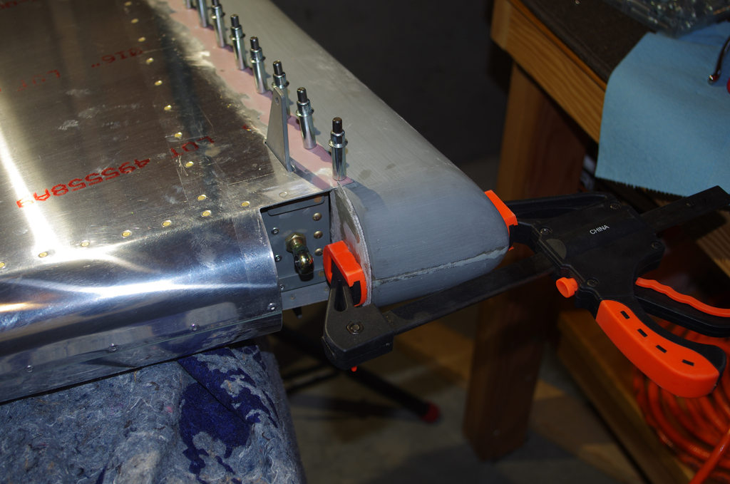
 Here are the raw and final fits on the passenger door aft guide. Getting the pin hole aligned properly took time with hand filing. The final gaps are good.
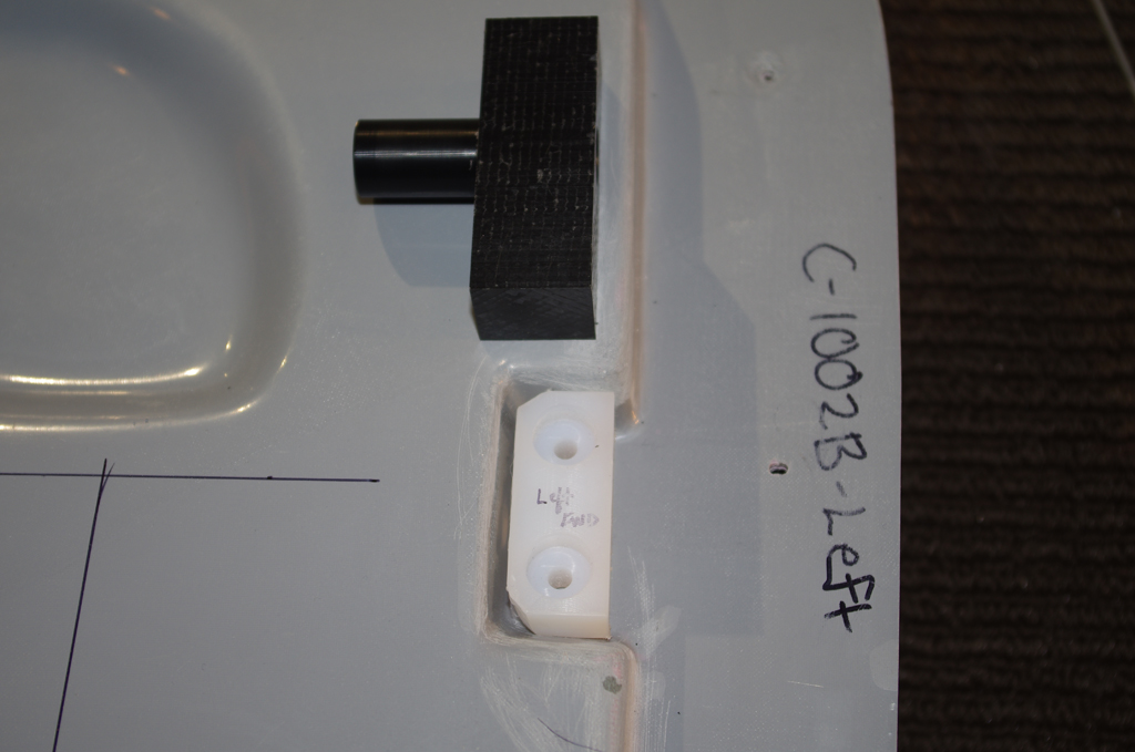
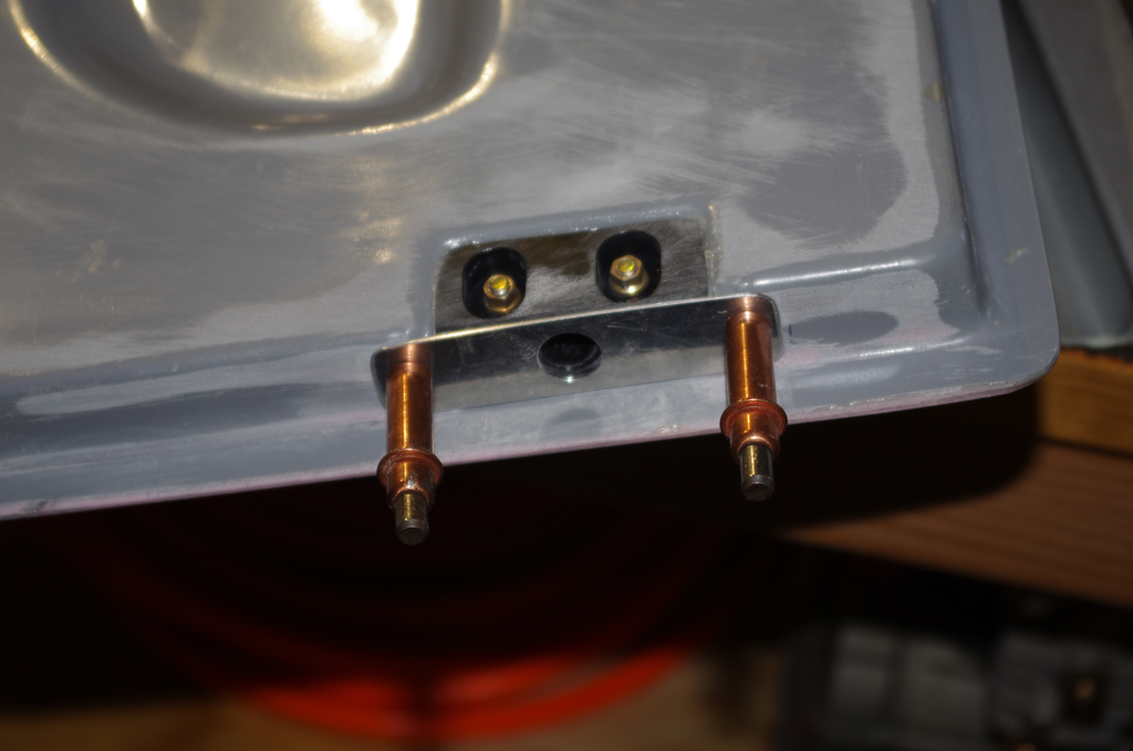 Here is a passenger door forward guide. Much easier since this is a straight piece. Now everything is ready for alodine/prime and covering the pin block with resin.


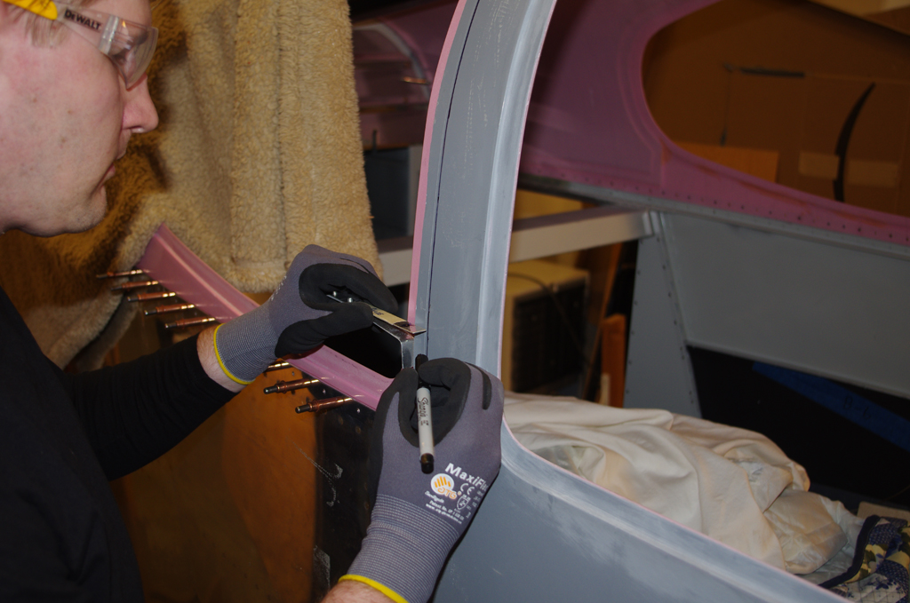


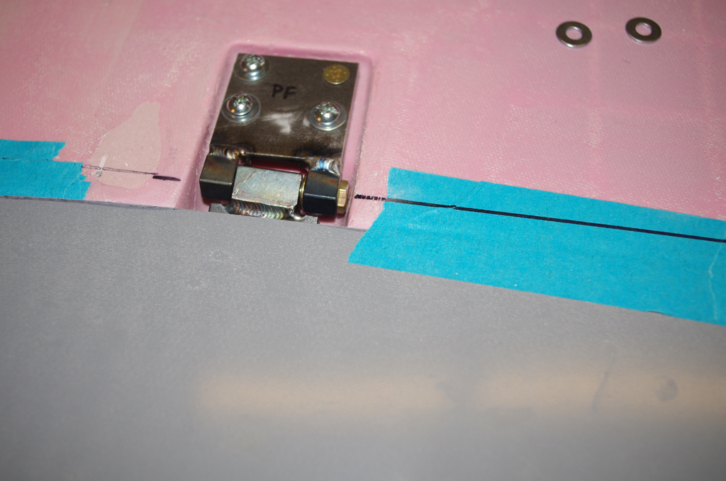
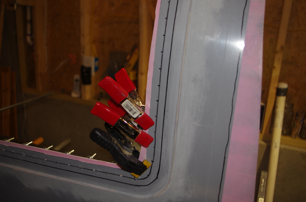
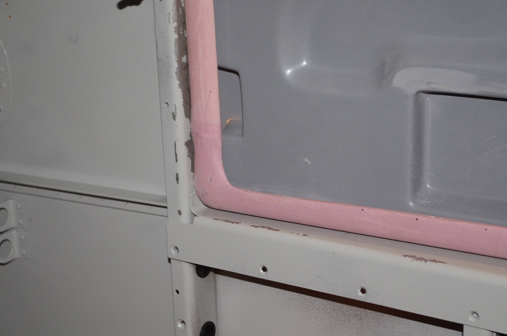
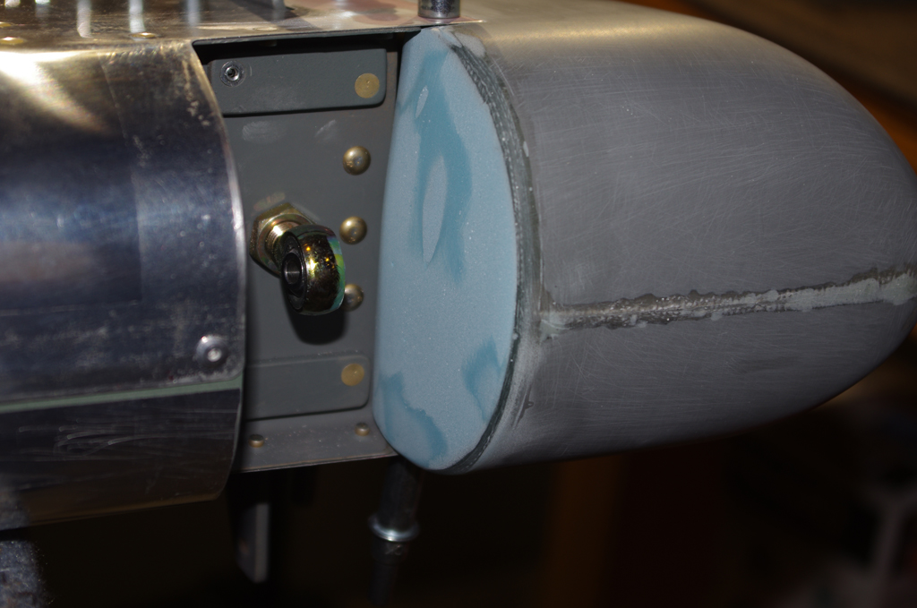
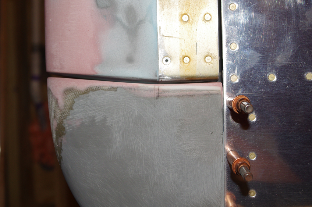
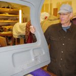
 Here is a closeup of the door against the cabin center column. The next step was tape the roughed in door into position, get ready to install hinges.