Moving Day

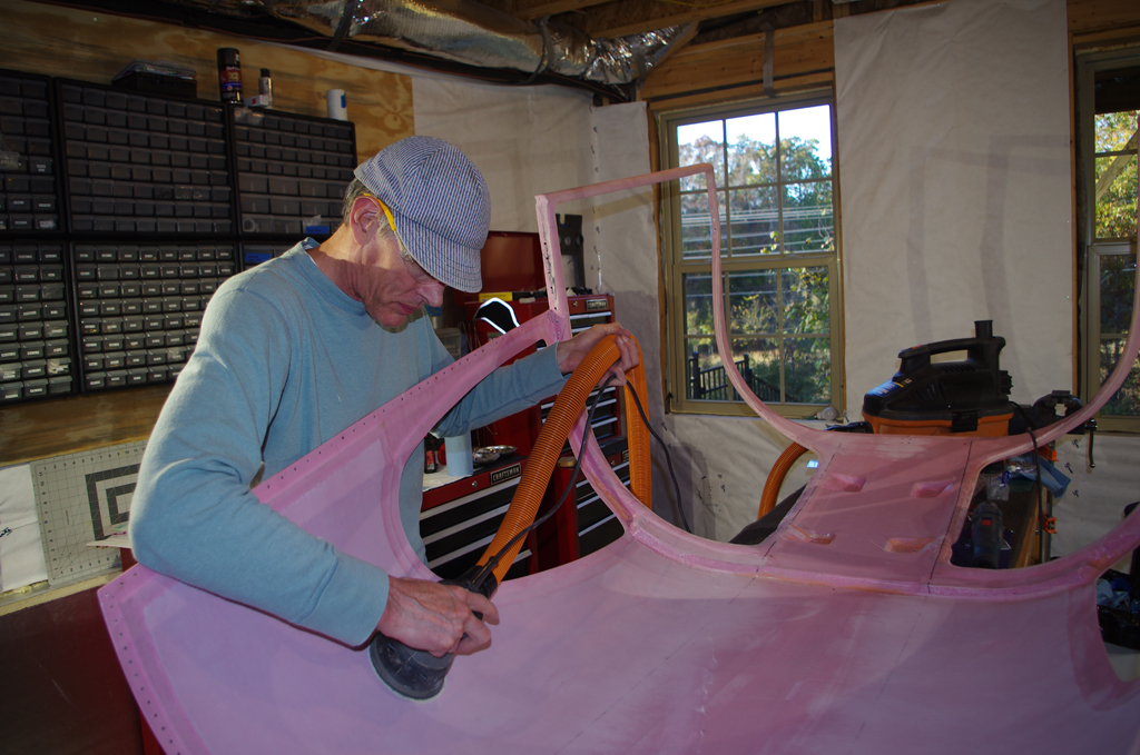
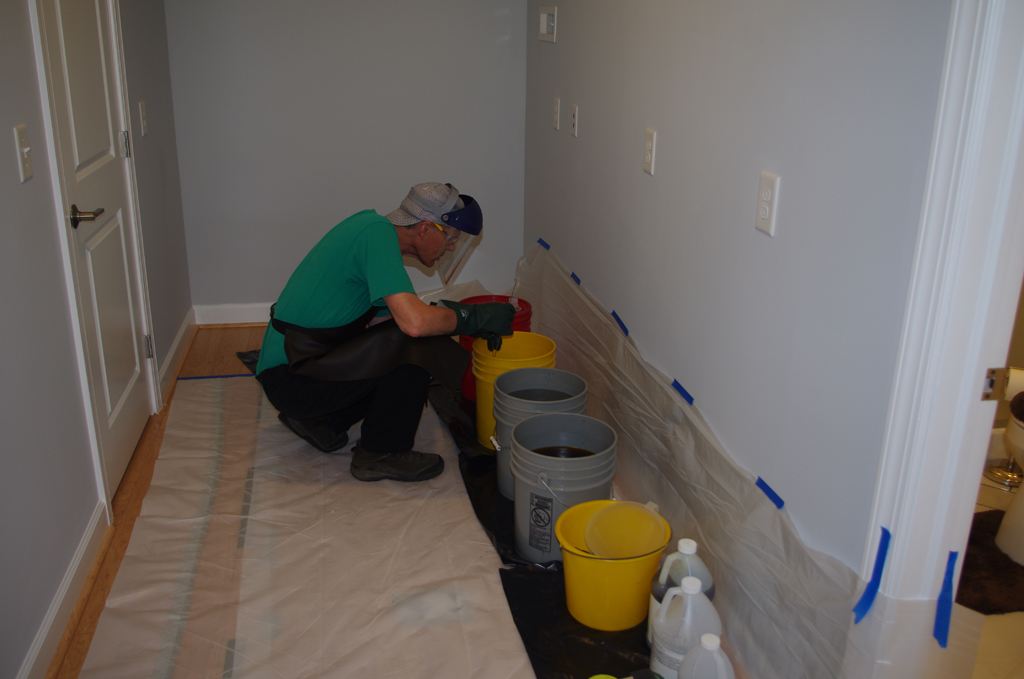
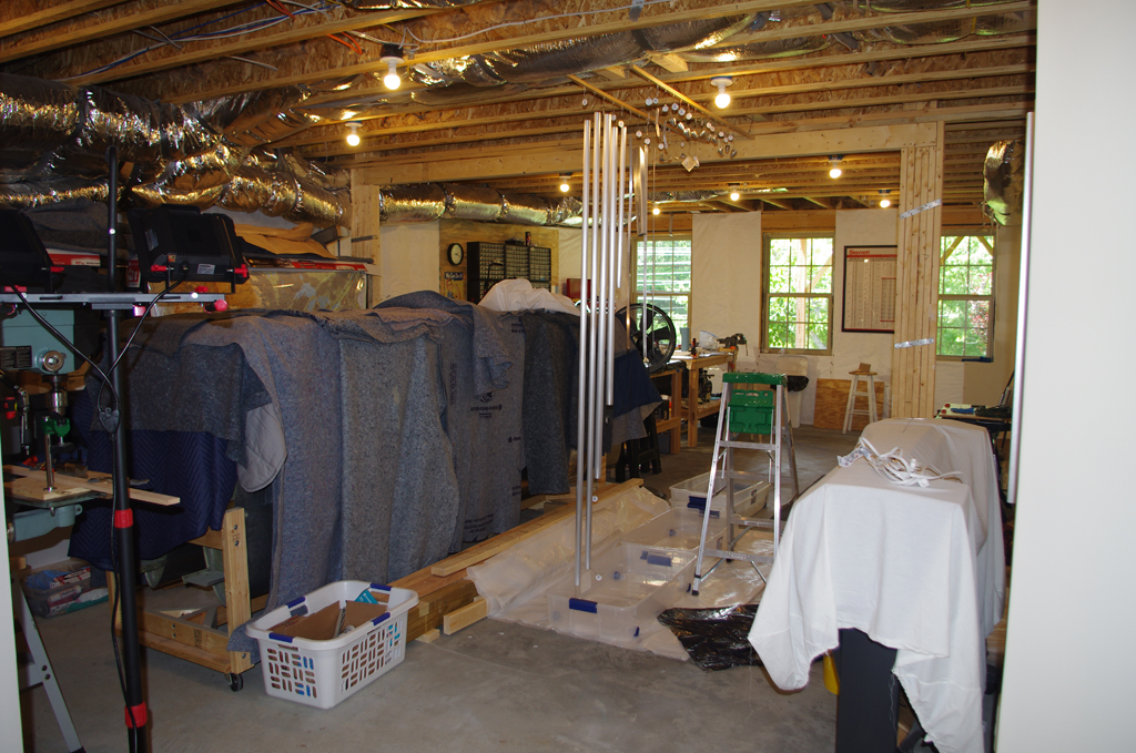
After about four years in a rented facility, I moved the fuselage to Tal’s workshop for interior painting and fitting mechanical systems.

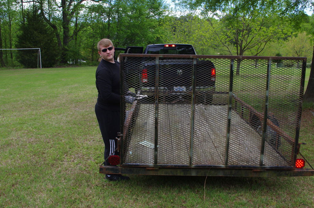
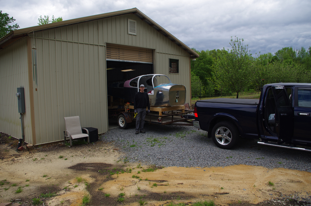
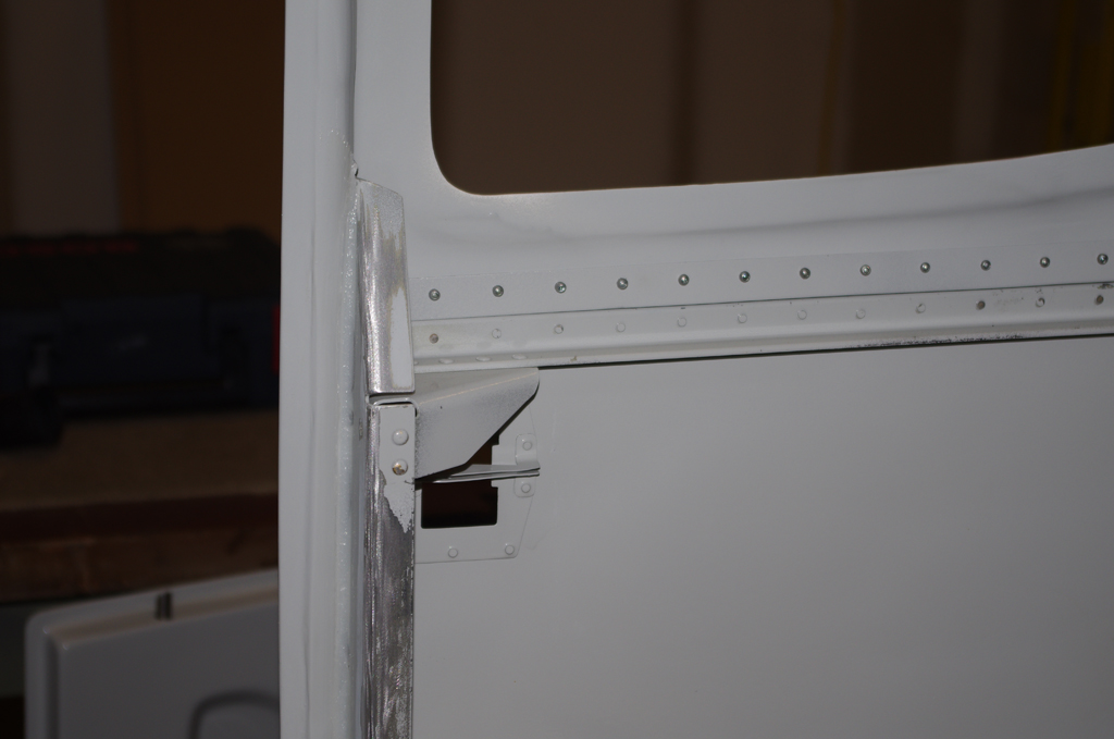
Work has progressed on the fuselage where most of the structural items are complete.  Now a focus on installing electrical, fuel and flight controls can proceed.  First up, however, is final internal painting at Tal’s shop.  Here Eric and I pickup the trailer for moving the fuselage.


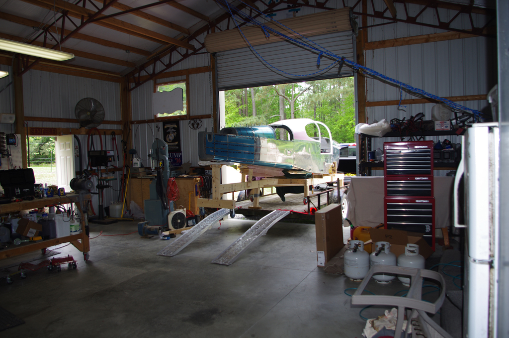
Using the wooden jig certainly helped rolling the fuselage up the portable ramps onto the trailer.  The roughly 10 mile drive to Tal’s shop was on back roads at max of 30mph.  It was a nail-biter for me, as 5 years of work was exposed to road hazards.  Fortunately, the trip went well and safe arrival.


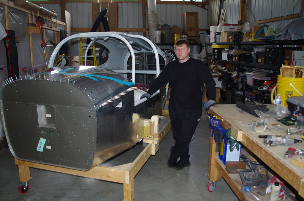
Unloading the fuselage also proceeded without incident.  My immediate next actions are clean-out the rented shop first to get the deposit back.  Then on to plane things…


Canopy, Doors, and Custom Parts

Work has continued on plane parts, though the frequency of my posts has diminished since the beginning of the year.  Here is a quick catch-up of recent activities.

The fuselage sill is filled with two-part resin/colloidal silica mixture just prior to dropping the canopy into place.


The lower retaining screws are locked into position while the resin cures.  Next the canopy and mid-skins are pop riveted together along both sides.  These two actions permanently attach the canopy to the fuselage.


Here are exterior and interior views of where the canopy and mid-skin meet. Overall a nice result.


DOOR HINGE PIN BLOCKS

The PlaneAround center cam gear block is located under the gear mechanism and then drilled/screwed in tightly.


Next the door pins are replaced with custom turned 5/16″ bolts to indicate the exact locations of the bulkhead through-holes.  The right photo shows the resulting latch pin location.


Finally the outer pin blocks are positioned to force the door down and in when the door lever is activated. Right now the fit is very snug, but I expect this will loosen a bit over time.  One this is for sure with this configuration, those doors will not be coming off the airplane in flight!


Baggage Door Hinges

I was not happy with fit or configuration of the original baggage door, so off came the larger hinges.  These were replaced with smaller hinges, and pins moved to a middle insertion point.  This allowed the relationship between the door, hinge and outer skin surface to be flush, as compared to having the hinges sticking out to allow pin insertion.


Custom Parts

Moving heavy objects around in the basement shop will be helped with a few custom-made skates.  These are made from 2×4 steel beams, 5/8″ drill rod at 10-2RS sealed ball bearings.  The plans are from the internet with no welding required, just proper alignment in the drill press. Eric will make 3D printed end caps to hold the skate axles in place.

Overhead Console (2)

Bonding the overhead console and painting the canopy interior were completed over the holidays.

Lord 7545A/E two part epoxy adhesive is combined through a static mixer tube with 21 cross-linking elements, then spread generously along the flanged edge of the Aerosport Products carbon-fiber overhead console


Clecoes, weights, spring clamps and sandbags are used to hold the console in place while the adhesive drys.  Some folks have performed this operation with the canopy already on the plane, but doing it with the canopy overturned allows gravity to be my friend.


After 24 hours of cure time, the Lord adhesive has finished bonding the surfaces together. Next is blending the overhead flange into the canopy interior surface.  Multiple layers of Super-Fil are applied and sanded until the transition between parts is invisible.  Layers of Poly Fiber Smooth Prime are rollered onto all the fiberglass surfaces.


The Smooth Prime is sanded in final preparation of priming/painting the canopy interior.  The standard PPG DP48LP Primer and DCC Concept paint will be applied as with all the other interior components.


Staged, degreased, and ready for treatment in Tal’s paint booth.


And here are the outcomes after two coats of primer and one coat of paint.  I think these turned out very well.


Cabin Doors, Custom Parts (2)

Installation of final door hardware and fabrication of custom hinge pocket covers were the topics for a few weeks.

Door handle, gas strut attach bracket


Aerosport low profile latch mechanism, interior and exterior views


adding magnets to latch pins, interim rod assembly, and final pin actuation


door hinges attached to door, preparations underway for fabricating the custom door pocket covers


fiberglass formed to exact pocket dimensions, cover plate clamped in place for adhesion to molded piece


initial sanding of canopy interior, initial installation of wire runs in forward canopy channel with E6000 adhesive


application of fiberglass over wire runs, which are actually 3/8″ air hose line.  build-up of inner door hinge pockets for even base for Airward nutplate pieces


forward and center canopy sections filled with Superfil and smoothed in preparation for bonding in overhead console


custom covers for the overhead console where the reinforcement bar comes up from the dashboard

Overhead Console

The focus for this week was modifying the AeroSport overhead console for vents, lights and switches prior to installation in the canopy.

Holes 2″ diameter for the air vents were cut into the template locations of the carbon fiber using a modified hole saw.  The outer teeth of the circular bit were filed down to provide an exact diameter.


Alignment of the LED light bases and ON/OFF switches for the rear seats were marked on masking tape, then drilled to fit.


The right photo shows the final placement for the rear fixtures. The left photo includes the custom GPS antenna cover plate previously fabricated.


The Aveo EyeBeam Touch located in the forward part of the console differs from the simple red LED lights installed in the rear.  It has adjustable intensity and can deliver either white or red light.


Nutplates were installed on a backer. The combined unit was then glued to the center rear of the console with resin.  This fixture will later secure a 3.5″ stainless handle to function as a cloths hangar for the baggage compartment.


Next actions are create a cover plate at the very front near the center bar, then attach permanently to the canopy.


Cabin Doors, Custom Parts

This summary covers a long period after Airventure, and prior to Labor Day.

The hinges finally can back after being chomed.  The results are good, and primarily based on the degree of preparation sanding I put into them beforehand.  Hinge pins are cut to length from stainless steel AN3-21 bolts.


Hinge pin locations are covered with resin, then sanded smooth.


The sand, resin, repeat process took a long time to get the surfaces just right.


Once the doors were ready, a batch of alodined parts was also prepared to prime/paint at the same time.


Tal’s paint booth was used to spray the doors and the parts.


HINGE COVERS

After painting the doors a build of custom hinge covers is needed to provide a good seal to the McMaster weatherstrip. Some modeling clay was used to partially fill the hinge pockets.


Then a few sheets of fiberglass were prepared, then pressed into position while still flexible.  Fitting and flush mounting remain after the sheets dry.


OVERHEAD CONSOLE / GPS ANTENNA MOUNT

I would like to have the GPS antenna for the Garmin GTN650 located under the canopy. However, the antenna attachment is too deep to fit in the gap between the canopy and the overhead console.  A custom cover was procured via 3D printing from AeorSport Products.


A mounting platform for the antenna itself was made from spare aluminum angle and sheets.


The platform is hinged, so exact angle with airplane centerline and flight angle can be achieved.


The hole for the custom cover is fabricated in the rear access panel.


Here is the final test fit showing the configuration of the cover, mounting bracket and antenna. Once the console is bonded to the canopy, the bracket can be permanently installed.

Engine, Propeller (Airventure 2018)

Eric and I drove to Airventure 2018 in Oshkosh primarily to order an engine and propeller from Van’s.

The show discounts from Van’s amounted to $1000 when ordering both components together, plus free shipping.  The engine is a 260hp Lycoming XIO-540-D4A5, while the propeller is a 3-blade Hartzell C3Y1R-1N/N7605C with a C-4582-P spinner (picture at left).  The engine will be added to the production schedule and should be built in 3-4 months.  The propeller is expected to ship in 4-6 weeks.  After much discussion, I was also able to get a free hat from Lycoming.


We stopped by SteinAir to ask a few questions about G5 autopilot connections, and VOILA! – they had a demonstration panel with nearly the exact equipment and layout I have been imagining for some time.  This is essentially how mine will be configured with a few alterations for internal lights, USB power and CO2 sensors.  Otherwise excellent.


These two products were obtained during the week. Both are very versatile for aeronautical and home use.  My first application was replace an air hose clamp with .032 safety wire. The combination works great and eliminates the sharp edges of the hose clamp when handling.


Empennage Attach (5)

Upon return from AirVenture 2018, I began assembling parts for the trim mount bracket.  These parts were alodined in an earlier batch, but needed to be primed before riveting.

The pushrod ends and small parts for the trim mount bracket were primed using PPG DP40LF with an old airbrush I had acquired almost 40 years ago.  The amount of paint applied is very easy to control and the very low volume in the paint bottle was perfect for this small batch. The idea is prime just those parts touching one another with the airbrush, rivet, then prime the larger external surfaces of the whole assembly with the regular spray gun.


The trim mount parts were clecoed together prior to rivet assembly.  A pneumatic squeezer with a longeron yoke was needed due to geometry requirements to reach the Trim Cable Anchor Brackets.


Here are the riveted Trim Mount Bracket Assembly and the Trim Servo Links. The next actions were to continue work on the secondary battery mounting platform, battery contactor mount brackets, and the ELT device mount.


Aileron Torque Tubes (2)

While the title of this post is about torque tubes, the general work this week is alodine and prime various other parts as well.

ALODINE

The process to wash, acid etch, rinse and alodine parts has been covered in previous posts. The difference here is performing the task in the climate controlled splendor of my new basement. Wonderful how not having to sweat at every motion seems to make the work go faster.


This batch included parts from control push rods, end caps, rudder trim mountings, cabin rivet backing plates and more accumulated during various stages of fabrication.  Unfortunately the alodine was at/near the end of its useful life, so only a light coating was achieved.  A new supply has been ordered, so a repeat of the last stage may be needed.


PRIME

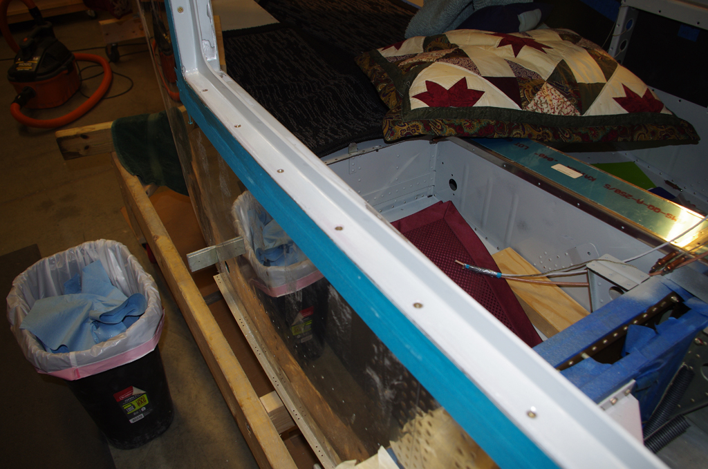
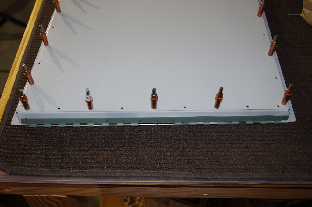
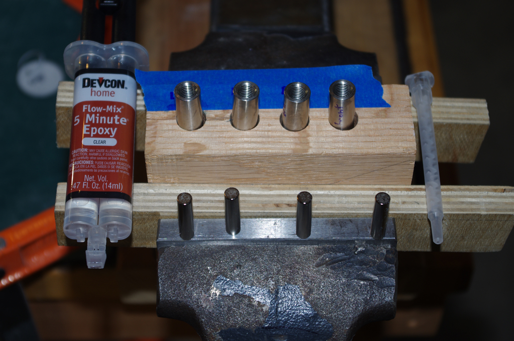
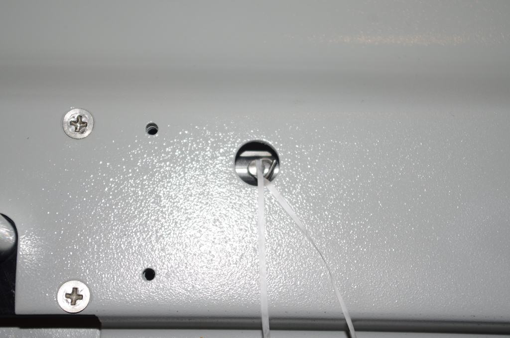
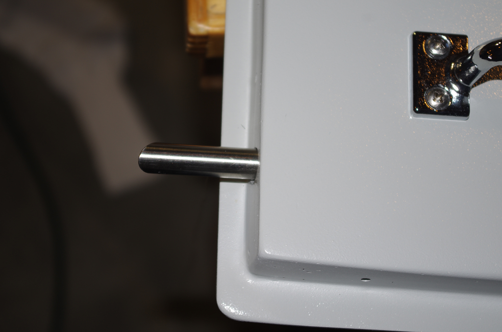
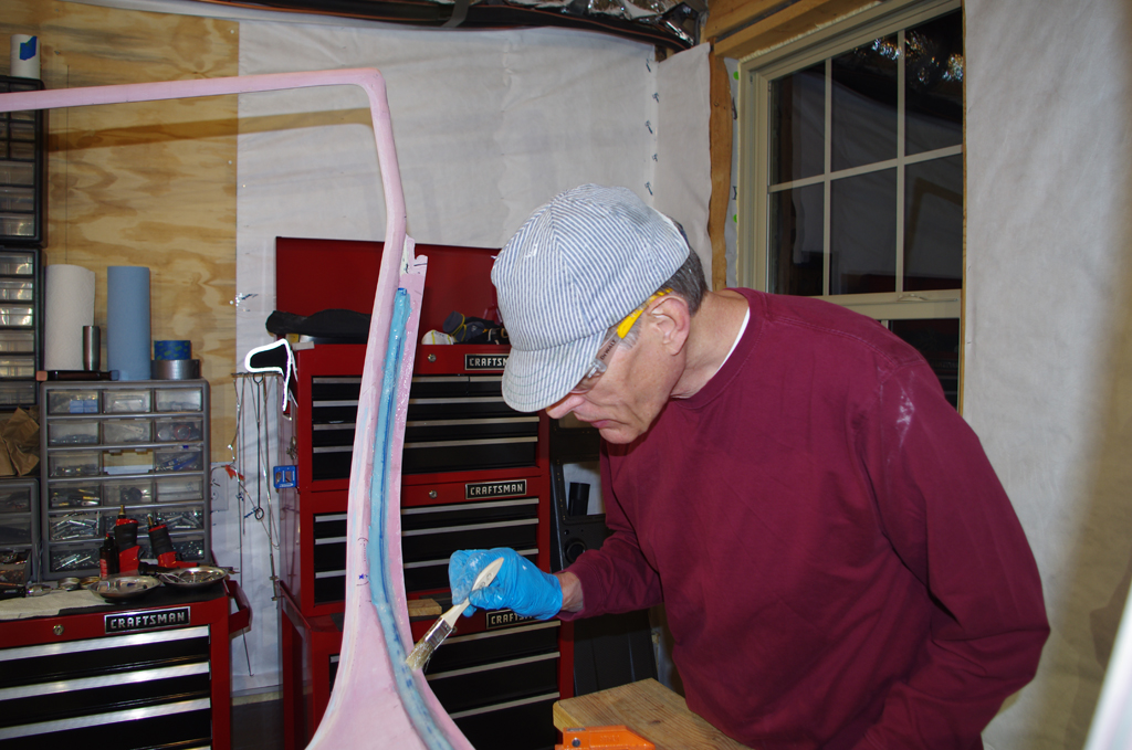
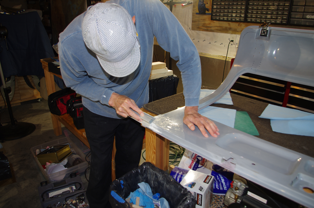
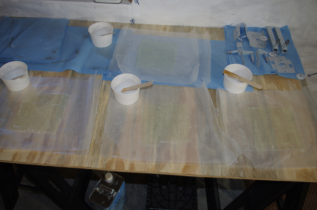
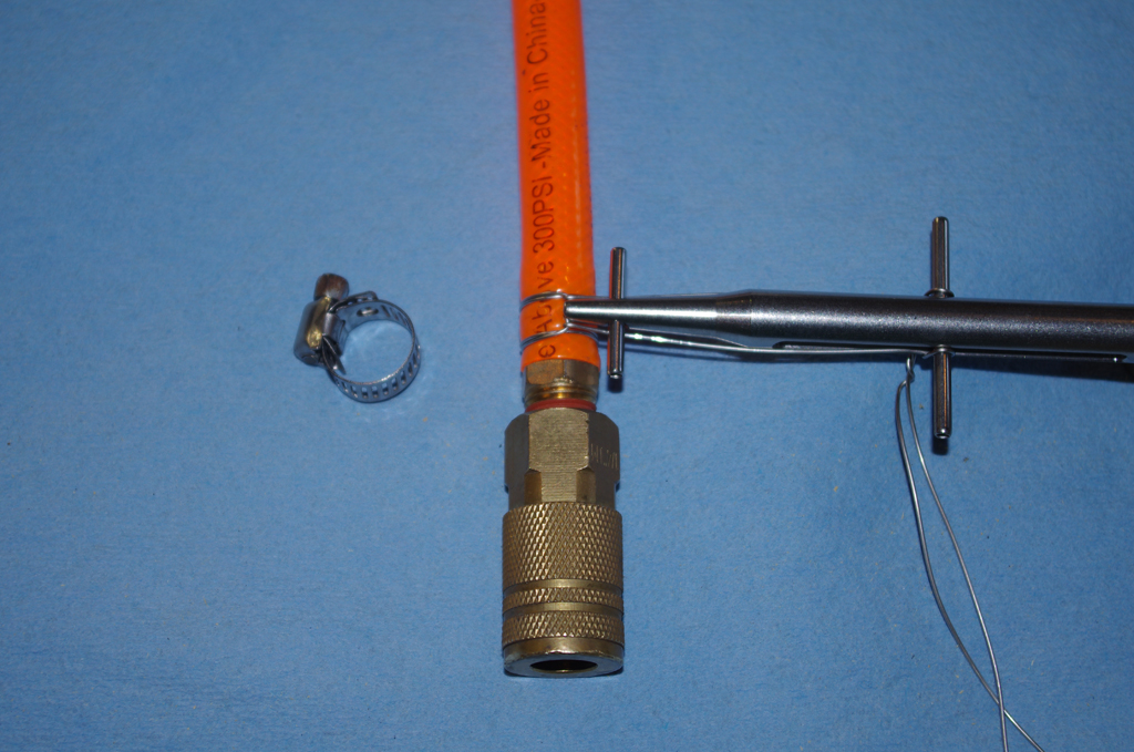
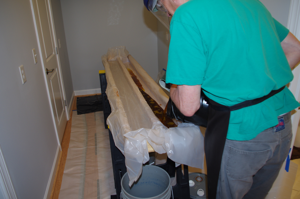
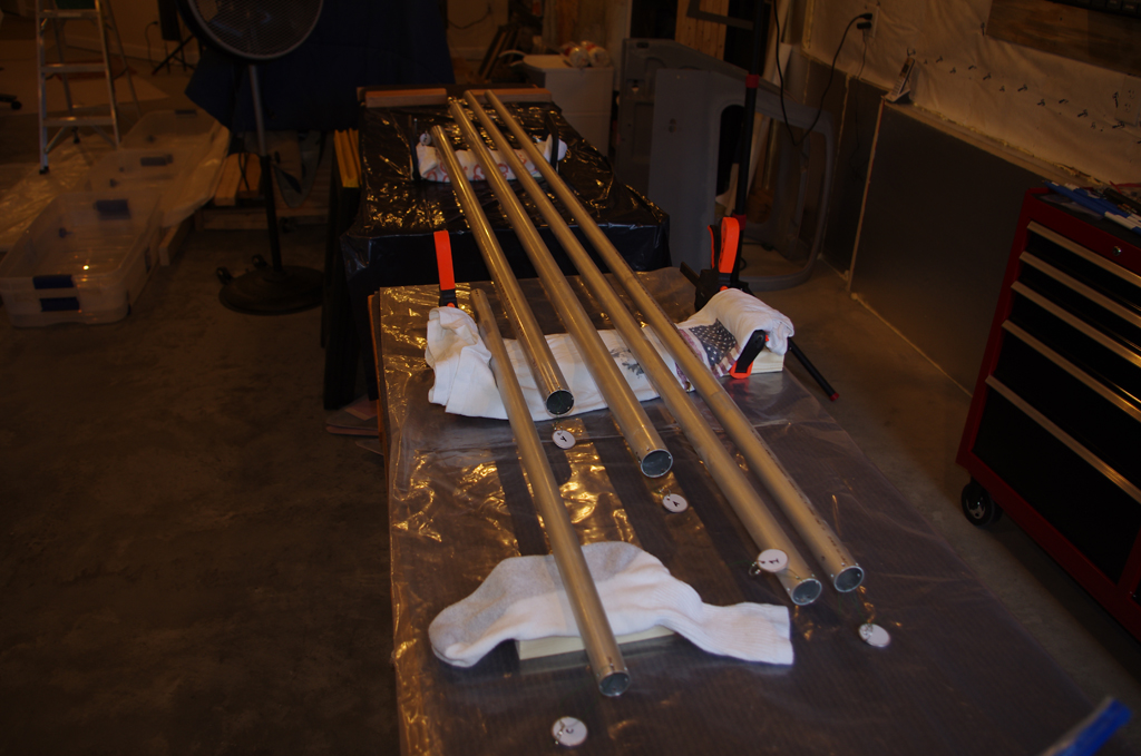
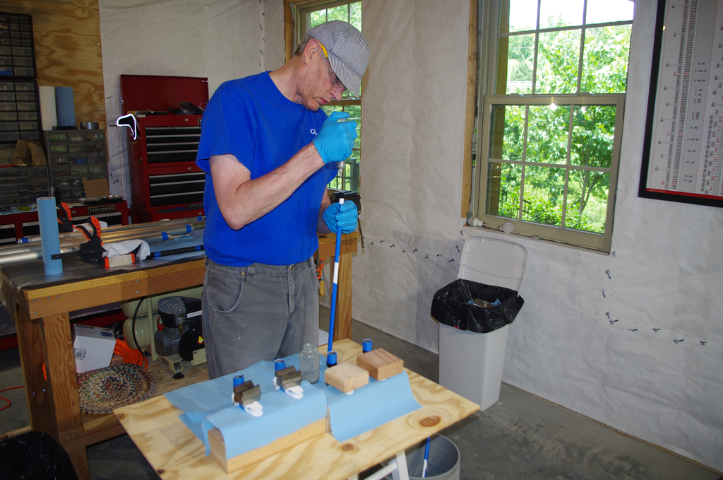
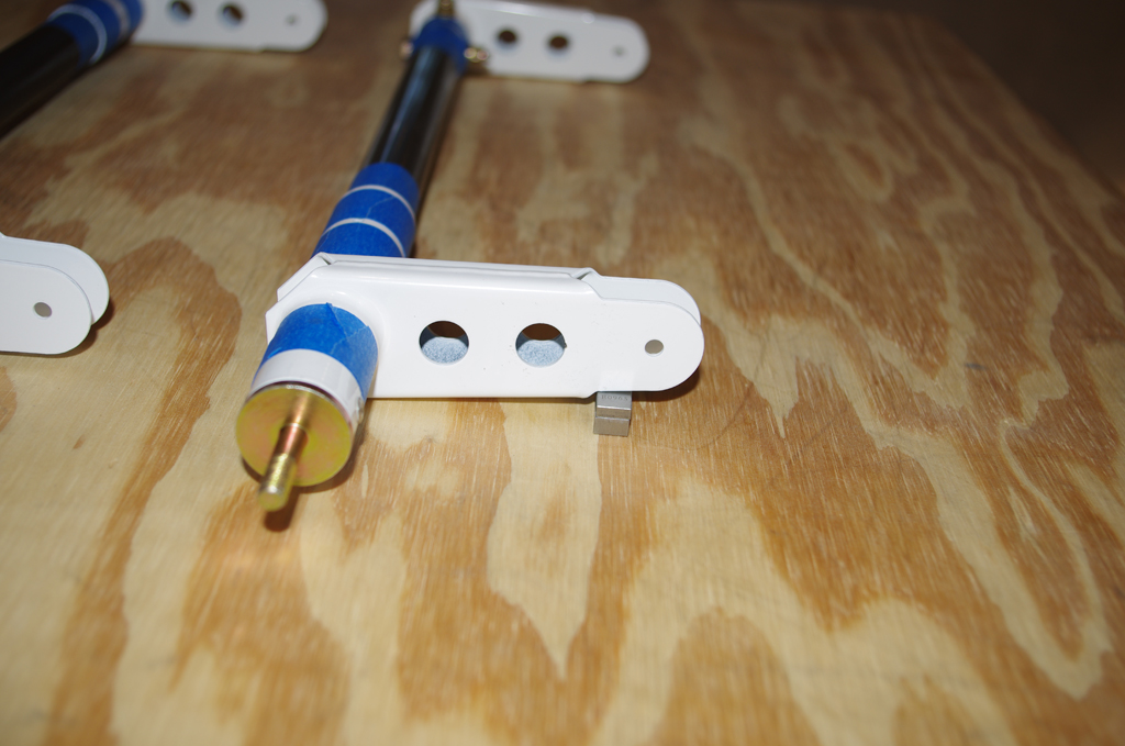
Priming the interiors of the flap pushrods and torque tubes is recommended in the plans.  A small quantity of two part, epoxy primer (PPG DP40LF) was mixed.  A small bit of acetone was added to help the primer flow better along the inner walls of these tubes.


Here the primer is injected in the open end of a flap pushrod.  The rod is then shaken to distribute the primer.  Excess material was poured out – though not much came out.  Most remained well attached inside the tubes.  Now let them dry thoroughly, then assemble as needed.


CUSTOM PARTS

New parts outside the plans are laid out for attachment to the center control bellcrank housing.  One is a auxiliary battery platform.  The other is a mounting bracket for two battery contactors.  The original Vans housing is configured for one contactor, I need two for the electrical system on my plane.


Aileron Torque Tubes (1)

The aileron torque tube assemblies were fabricated this week.

The aileron torque tube assemblies consist of a straight steel tube collars between powder coated torque levers  with threaded end caps.  The first step is insert the end caps in the torque levers and drill holes for MSP-42 rivets.  The right picture shows before and after riveting.


The drill press, two precision V-blocks, and clamps are used to secure the cut-to-length steel tubes inserted in the longer torque levers for  accurate alignment.  The desired outcome is fastener bolts perpendicular to each other. Very good result.  (I love that drill press).


Next the distance between the end caps is adjusted to 17 25/32″ overall length. Before drilling through the steel tube, the angle between the levers is clocked to proper alignment.  Here two gauge blocks are stacked to give the 5/16″ distance to make the angle called for in the plans.


The left picture is the drill press setup for the final bolt hole drilling.  The completed torque tubes need to be taken apart for priming inside and out.  This process will be done with a batch of elevator, aileron and flap pushrods.