Oil Door and Misc (1)

The oil door on the upper cowling will be modified from the original vans plans to accommodate a hidden hinge and camlock latches.  Also work on miscellaneous components of for the cockpit were started.

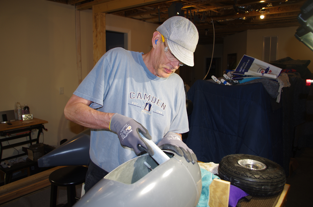
The first step was trim the fiberglass door part to fit snugly into the preformed pocket on the upper cowling piece.  This involved initial shaping with a Dremel cutting wheel, followed by hand sanding.  As with all the fiberglass work done so far, the default fits were just approximations – nothing was square, smooth or level.  While I tried to get the door as square as possible, a bit of distortion remained.


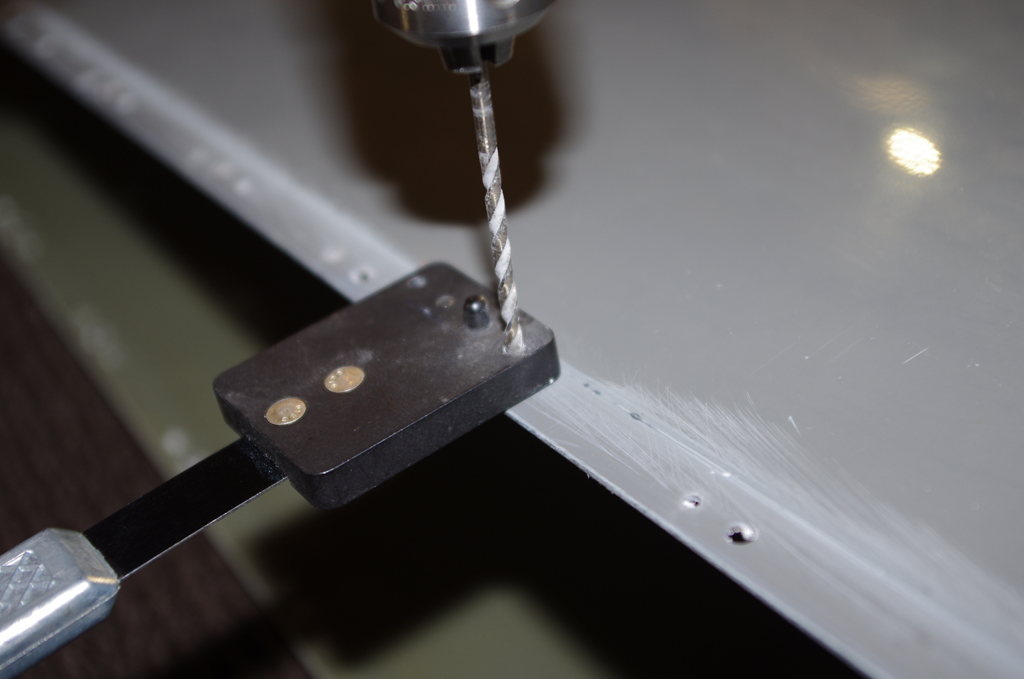
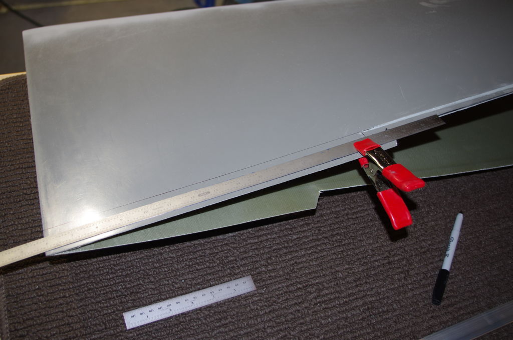
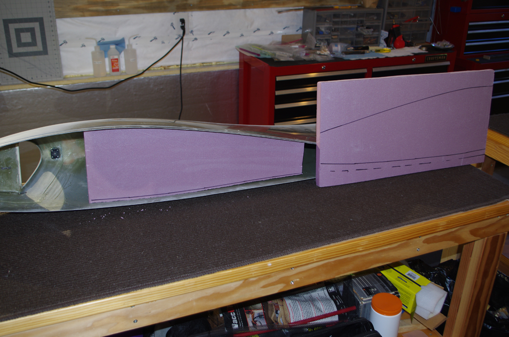
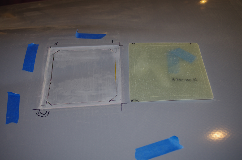
Next was measure the inner opening to the engine compartment.  I wanted the cut line as thin as possible, so the removed piece could be used to reinforce the outer door itself.  At left are the trim lines, at right are the first cuts with the Dremel tool.


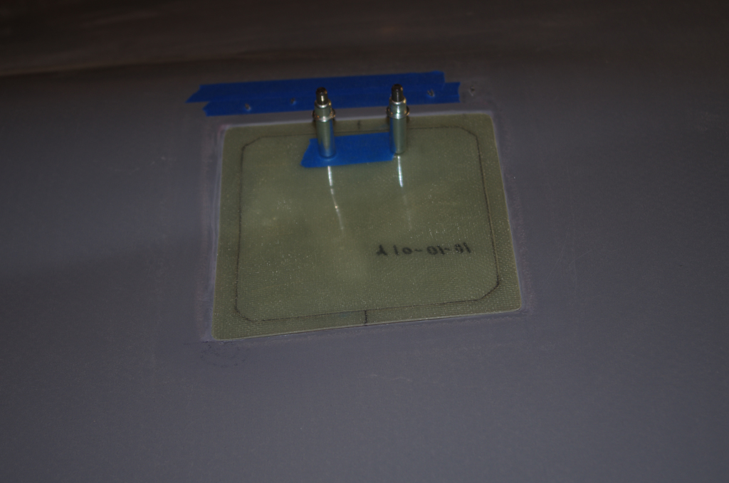
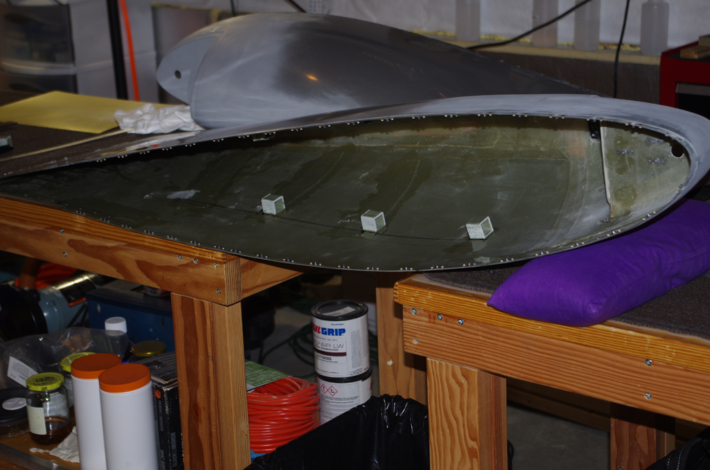
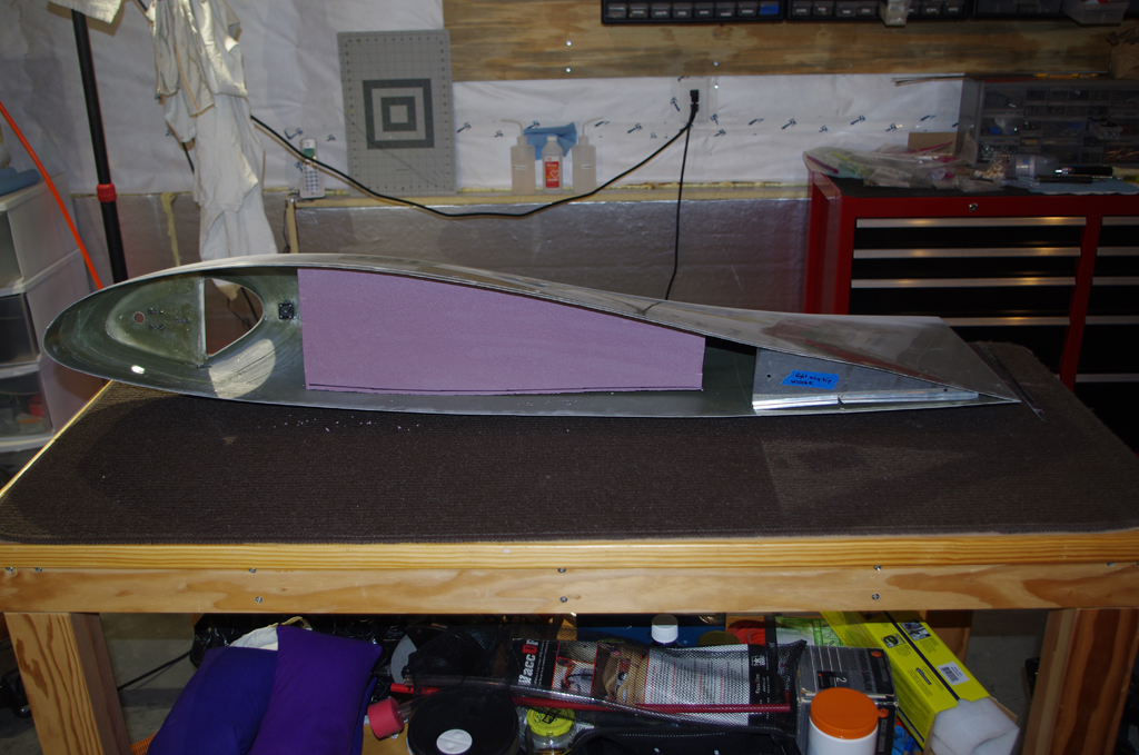
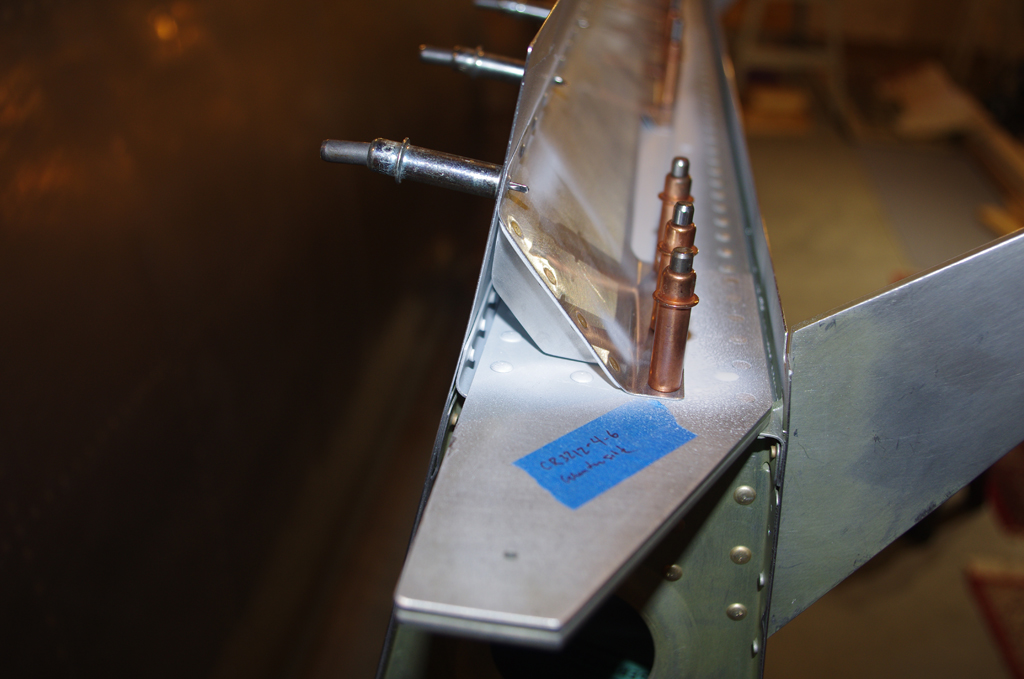
After the inner cuts, the hidden hinge was aligned and drilled. The initial fit was good.  Note the pink inner piece attached to the door.


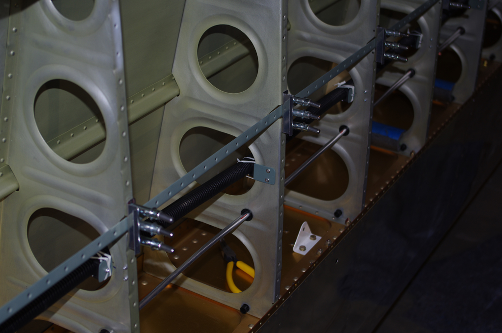
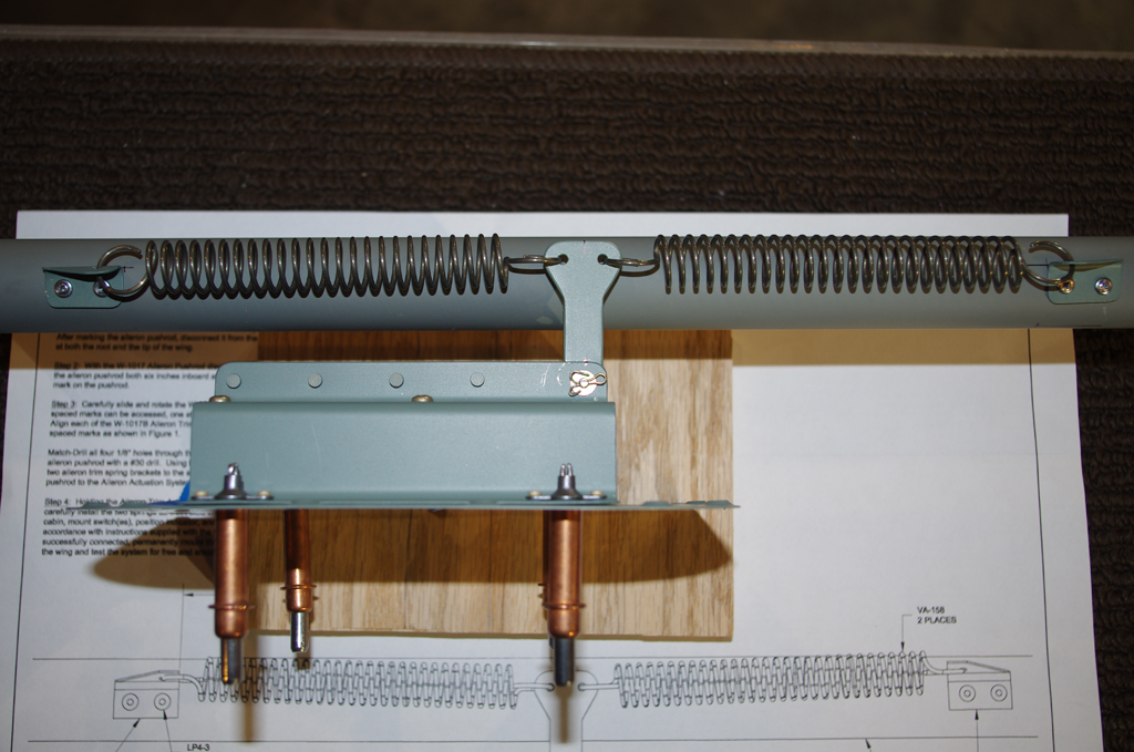
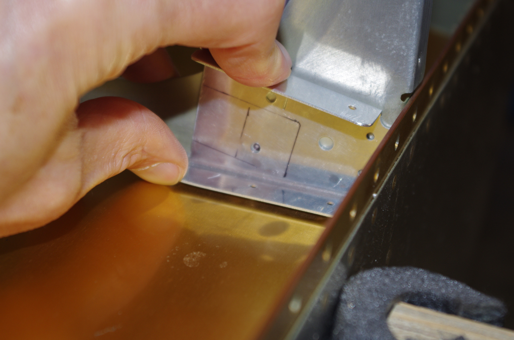
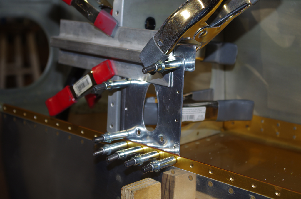
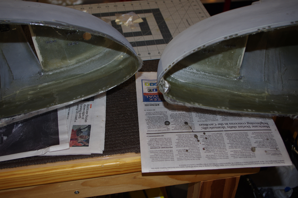
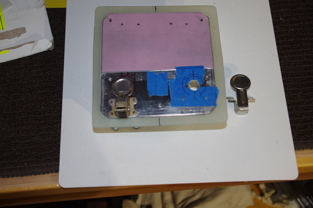
The trickiest part of this build was aligning the camlock latches to get proper clearance with the cowling, while still being tight enough to firmly fasten the door when closed.  The left photo shows a backing plate made to strengthen the door from pressure applied by the latch spring.  At right is an outer view of the finished latches.


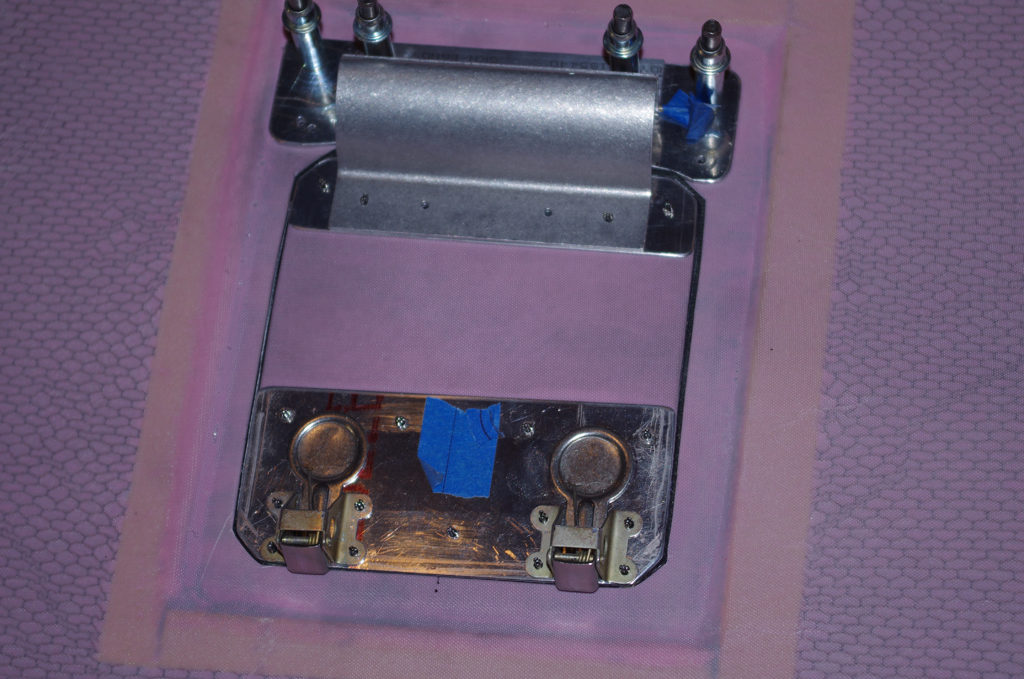
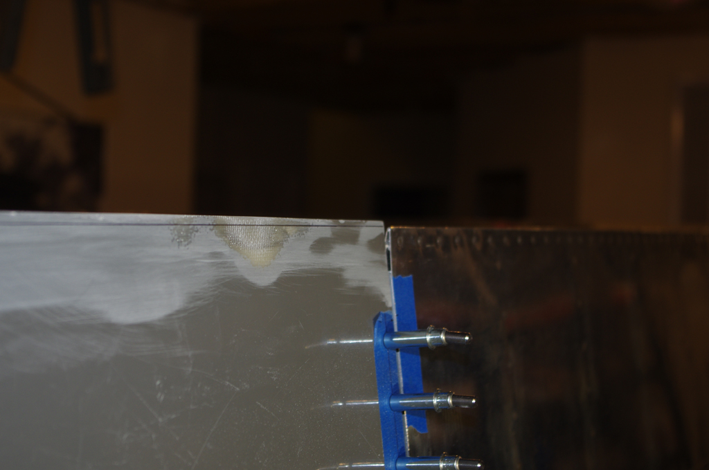
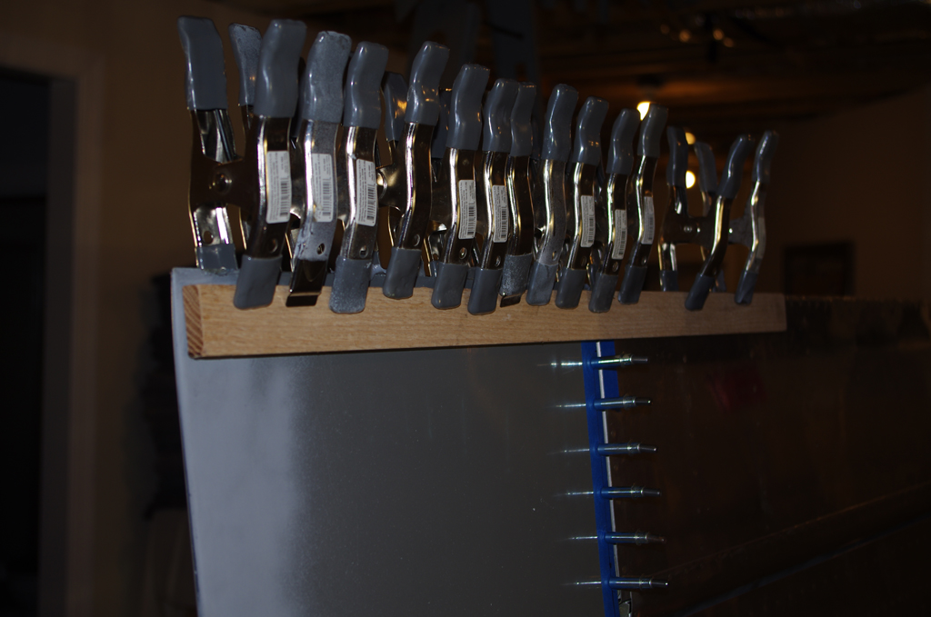
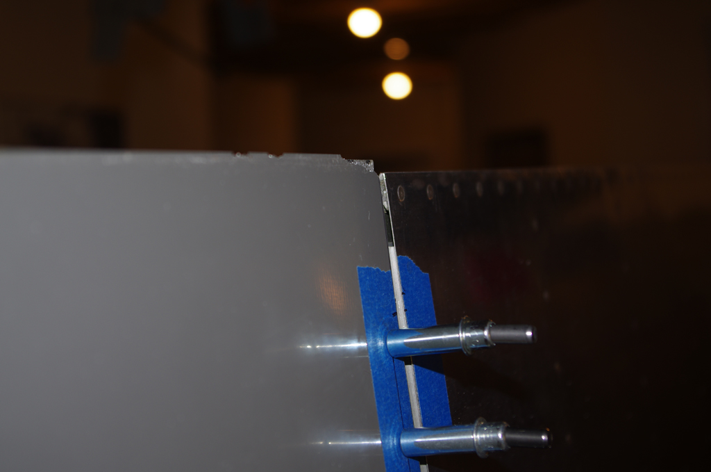
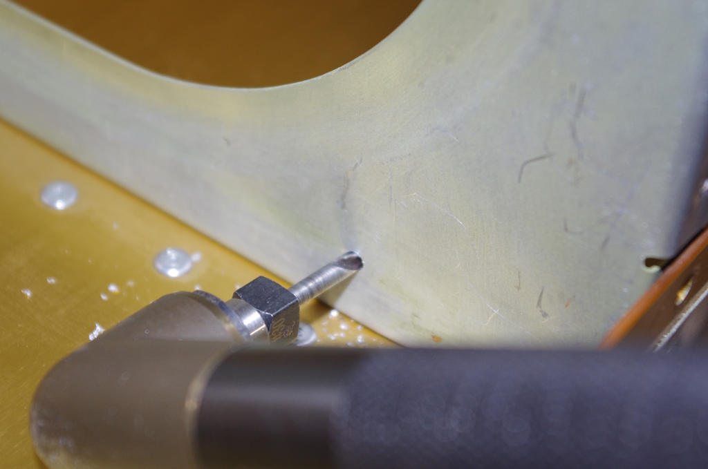
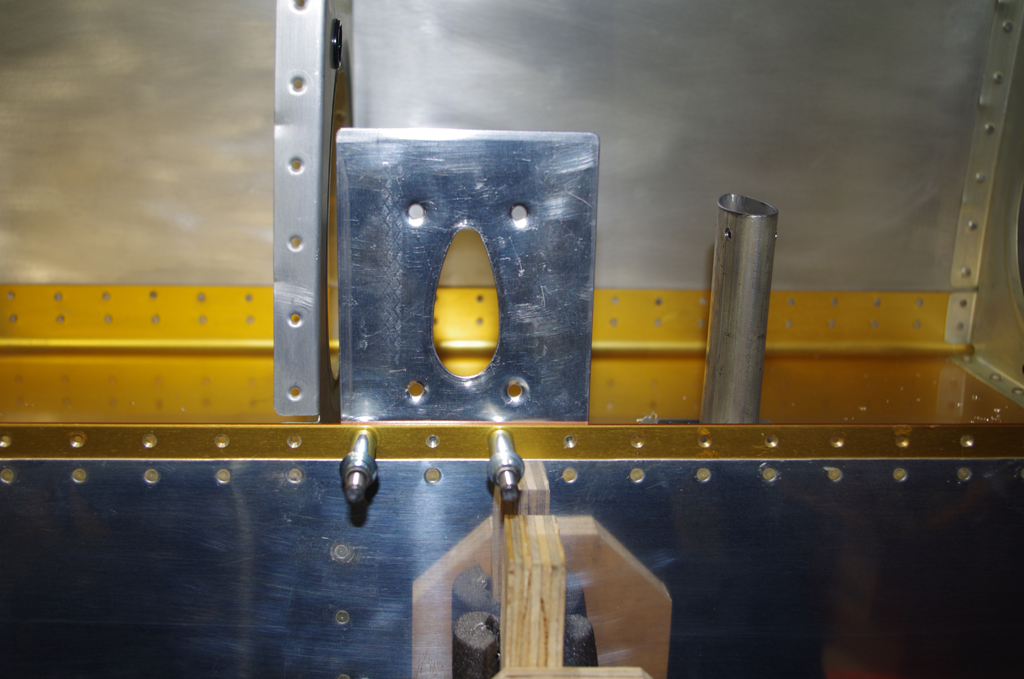
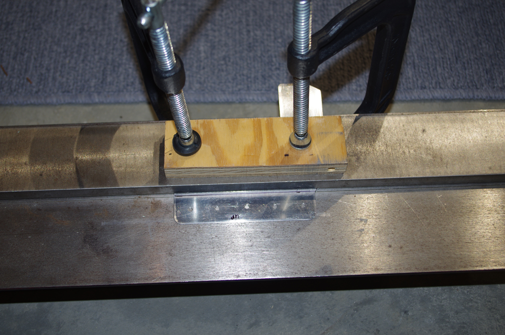
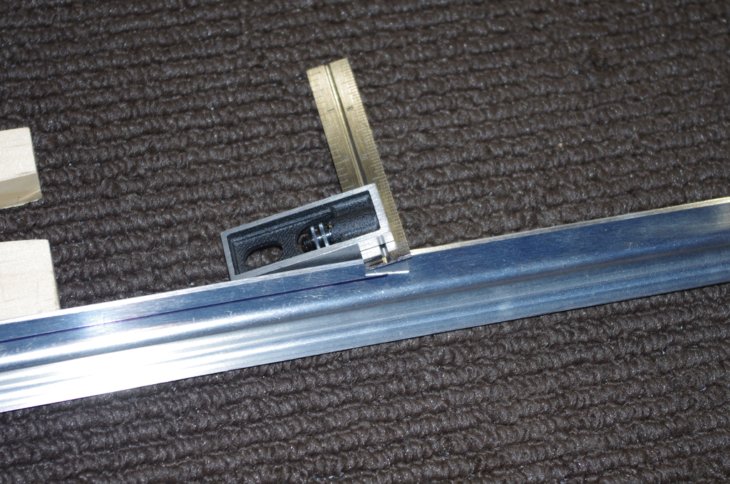
Two more views of the camlock latches.  Next to complete is a steel strike plate at the latch lever locations to keep the fiberglass rim from cracking or splitting.


INSTRUMENT PANEL

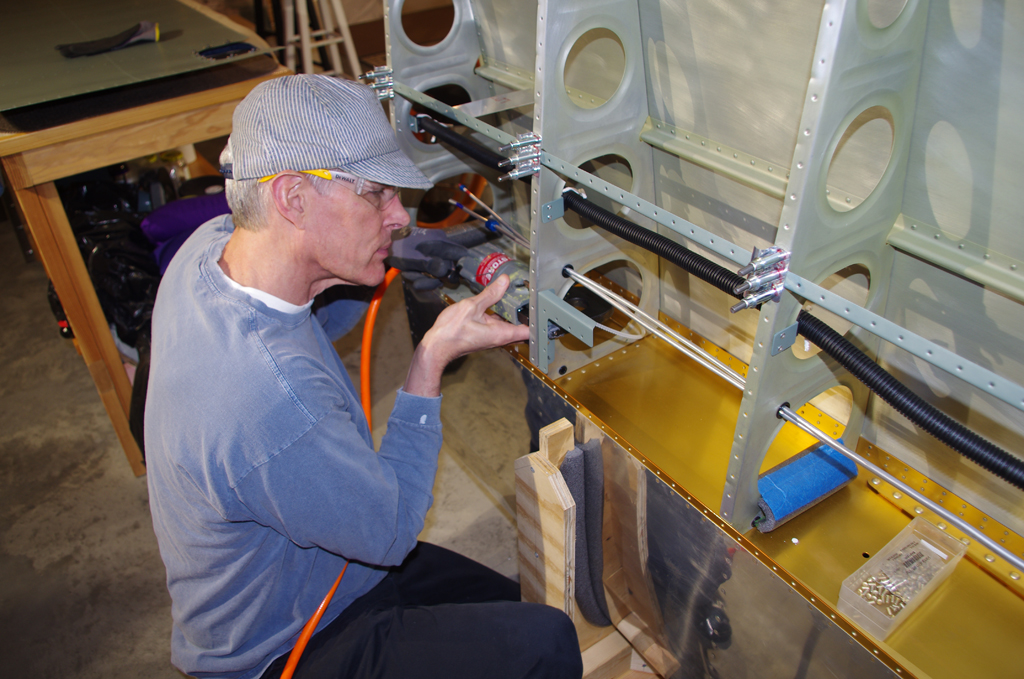
Holding the upper dashboard while fitting the instrument panel and electrical system can be a problem.  A jig to hold the panel in either vertical or horizontal position was created.


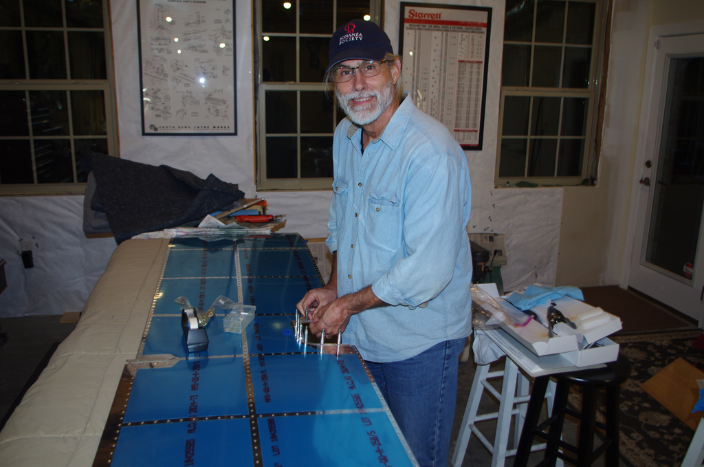
Here is the finished jig ready for work on the panel.


DASHBOARD GLARE SHIELD

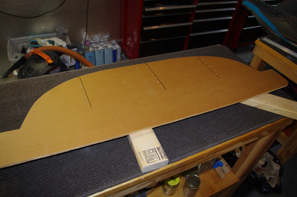
A template for the upper dashboard area was created on a sheet of construction paper.  This was then covered in wax paper (for release purposes) and covered with West Marine resin and two layers of fiberglass.


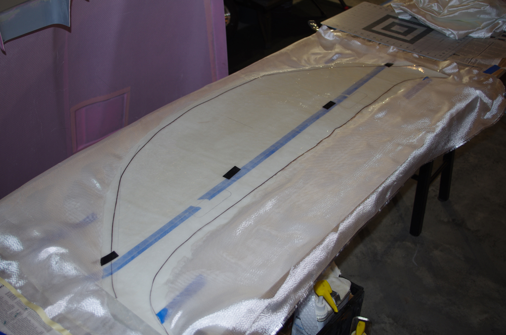
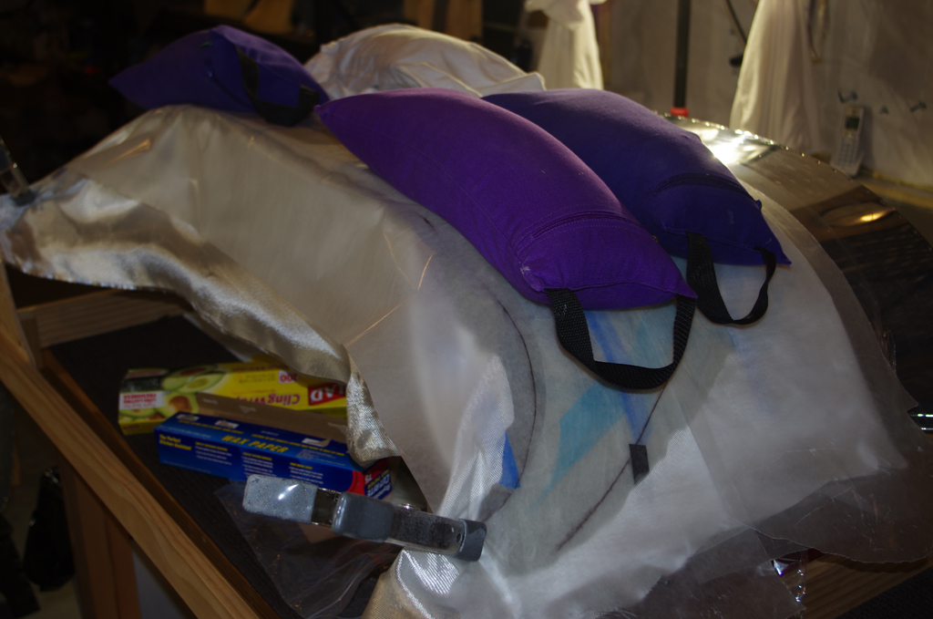
After the template has set for a few hours, but definitely before the resin hardens completely, the sheet was placed on the dashboard and sheet pressed into shape to match the curve.  Later the hardened sheet will be covered with trunk liner to provide an anti-reflective surface.   More on that in later posts.

Wing Tips (3), Pitot System

The 2019 holidays saw plenty of shop time for plane work with continuation of a variety of wing preparations.

PITOT SYSTEM

The pitot and angle of attack (AOA) aluminum tubes near the wing root were flared to accept unions-to-plastic-tube conversions.  Note the 37 degree angle and coupler nut are dry fit, no need for lubrication on these pneumatic AN fittings.


The pitot mast attachment bracket (fabricated in previous posts) was riveted onto the second to last wing rib.  The pitot probe tubes were then bent to about a 90 degree angle.


The aluminum tubes at this end of the wing were also flanged using a Parker Rolo-Flair tool.  The red and blue markings are colored Rescue Tape.  Blue for the pitot line, red for the AOA tube.


The flanged tubes were then arced backwards with an Imperial 368-FH bending tool. This configuration now allows connection of the pitot lines through the wing ends.  After the skin is permanently riveted the access will be limited.


Once the pitot tubes were finished, then the nylon wiring conduit was cable-laced into position.  A few custom jigs were made to hold the J-channel stiffener in perfect alignment with the wing ribs.  This stabilized the rib orientations while the conduit was laced.


WING TIPS

To finalize the wing tip geometry the flaps and ailerons were attached and placed in the “neutral position”. This is establish using a combination of the Aileron Bellcrank jig and moving the flaps to the upper, hard stop position against the rear spar. The final angle was adjusted to 3 degrees with a few thin shims. The red Gust Lock in the photo holds the flaps/ailerons together at the same angle.


Here are the before and after pictures of the final wing tip alignment.  The steps described below were needed to make the corrections.


First the rear edge of the wing tip was separated with a saw. This allowed the end panels to slide against one another.  The wing rib holes were drilled to even spaces.  The split wing tip was then attached to the wing, and the wing rib progressively clecoed from the front edge toward the rear.  Colloidal silica resin, a straightedge and spring clamps were used to align the rear edge with the neutralized flap/ailerons.


The final edge was allowed to cure for 48 hours. Then the overage from the wing tips measured.  Eventually this extra material was removed (more on this in a later post).  The overall outcome was very satisfactory.


Another addition to the wing tips was a stiffener rib.  This helps prevent “oil canning” in flight due to air pressure on the wing tip surfaces.


WING SKINS

With the wing tips nearing completion and all the other mechanical elements in place, time to start riveting the lower skins.  This was a time consuming, two person effort. The right wing took about 10 hours to finish. We are just starting on the left wing now.


Electric Aileron Trim

The aileron push rods must first be set into a ‘neutral’ position before the trim servo motor can be properly aligned and measured. The objective of this exercise was attach the aileron trim spring brackets.

The left picture shows attaching the aileron push rod end to the outboard pivot actuator.  The inner push rod end connects to the aft arm of the aileron torque tube in the wing root.  A bearing for the torque tube must first be installed in the tank spar.


The sealed tanks (see below) were then installed in the wings – capturing both ends of the torque tubes during the fitting process. These tubes could be installed with the tanks already attached, but the process was much easier with the tanks off.


Here are close-ups of the torque tube connections in the left wing.  Notice the jig in the left photo created to position the push rod.  The final push rod end lengths were adjusted to neutral with the jigs, then the jam nuts were tightening to hold everything firm.


Now began fabrication of the trim servo bracket.  After cutting, smoothing, and deburring  the trim bracket was provisionally assembled with clecoes. The inner left inspection plate was then match drilled as the base for the trim bracket.  A coat of SEM Self-Etching primer was applied to all surfaces.


Top and bottom views of the assembled trim servo in the bracket and the modified inspection plate.


The supplied Ray-Allen trim switch was connected between a 9V battery and the servo motor.  A Fluke voltmeter confirmed electrical contact during operation.  The motor takes ~27 seconds to move from the inner to the outer position.  This measurement and actually marking the two position limits were used to locate the center of travel for the aileron trim arm.  This measurement was transferred to the neutralized push rod via a parallel angle channel and a square.


The photo on the left shows prior to riveting, and on the right the final configuration.  It will be a challenge to install the springs once the push rod is permanently installed in the wing.


FUEL TANKS

=============

The quick build fuel tanks were removed for leak testing prior to aileron push rod adjustment.  My A+P friend Terry filled each tank with 30 gallons of aviation fuel for a week.  No leaks!   Once final wing assembly is complete, removing the tanks for leak correction would be very difficult. So just for good measure, all the rivets and seams on the spar side were also covered with a generous portion of Van’s tank sealant (similar to ProSeal).

Bottom Wing Skins (2)

A series of miscellaneous activities were performed on the wings in the last few weeks.  This work was staged before any final riveting the bottom skins, as access is so much easier with the skins still off.

The quickbuild wings come with a main wiring channel in each wing. These roughly 5/8″ diameter hole have nylon inserts and are intended by Vans for the wingtip wire bundles.  Because of added electronics for heated pitot, aileron trim, autopilot servo, and the like, I wanted addition channels (thus the custom wire brackets from previous posts).  I also wanted dedicated grounding lines to the wingtips, so additional channels were created.  Here a template is used for reproducing the hole placement in the wing ribs.


Once measured, the 7/16″ holes are punched and then drilled with an angle head holding threaded bits.


The final configuration of each wing has three available channels, two through the ribs and one wiring chase attached to the custom brackets.  For the left wing, the 1/4″ soft aluminum tubes for the pitot and angle-of-attack (AOA) indicator will be fed through the larger of the runs through the ribs.


==================

PITOT MAST

A Gretz mount for a Garmin heated pitot needed to be crafted in the second from tip rib bay.  This location is further outboard from the Vans plans, but allows greater access for maintenance and adjusted once the bottom skin is attached.  On the left a backing plate is clecoed in place to mark the skin for a through-hole.


A sheet metal bending brake formed another  bracket for between the rib and the pitot mast backing plate.  The right photo shows the bracket clamped prior to drilling through the rib.


Here the #8 screw nut plates are attached to the pitot mast.


Two different views of the pitot mast – clecoed in the final position and showing in relation to the modified skin.


===========

MISCELLANOUS ACTIONS

Rich visited for two weeks to help with flap gap riveting, inspection port assembly and other miscellaneous activities.  We used CherryMax rivets of type CR3212-4-6 countersunk (qty. 6), and CR3213-4-2 (qty. 14) and CR3213-4-3 (qty. 6) round head rivets on the inner flap gap openings of each wing.


The wing bottoms were treated with SEM Self-etch primer from a rattle can prior to having the inspection port nut plates attached.


===========

AILERON ACTUATION

To properly locate the spring attachment points on the aileron push rods, the actuation levers and torque tubes must be installed and the rod oriented in a neutral position. More on that in  later posts.

Custom Wire Brackets

The default wire channels from Vans do not include provisions for additional devices I will be installing in the plane (auto pilot servos, heated pitot mast,  aileron trim servo, dedicated grounding wires, …).  In addition a nylon conduit would allow easier future maintenance than the holes through the ribs.

A series of custom wire brackets were fabricated from 1/16″x 1″ x 1.25″ angle aluminum. The band saw fence was setup to cut raw brackets the same width.


Here they are, one for each wing rib to span.


Next use a jig on the drill press to accurately reproduce the hole pattern for each bracket.


Cut, drilled, prepped, primed, and ready to assemble.  The 5/8″ nylon conduit will later be cable laced to the holders.  Zip ties could be used, but I prefer the endurance and flexibility of the cable lace.


Here is a through shot of the conduit run laid out with string. Then installation begins…


As with many of these operations on the wing, having the bottom skin still off makes everything so much easier.

Wing Tips (2)

This is placeholder text for details to be added later.

aaa


aaa


aaa


aaa


aaa


Here the fuel tanks are being removed from the quick built wings. The next step is leak test them with real aviation fuel, reseal as needed before installing back on the wings.

Wing Tips (1)

Once the bottom skins are ready for installation, work can begin on the wing tips.

The wing tip edges must be shortened to fit into the roughly 3/16″ (10mm) gap between the last wing rib and the skin edge.


After initial trimming for fit, the wing tip is #40 match drilled with the top and bottom skins.  Start at the forward portion of the wing and work backward (up in the photos).


Other builders highly advise reinforcing the very thin fiberglass web in the wing tips to prevent ‘oil canning’ both during flight and on the ground (spectators leaning on your wing).  This shows a provisional fit of 1″ rigid foam, which eventually will be glassed into place mid-section of the wing tip.


While the wing tips at this point are far from completion, having them provisionally hung on the wings is a great feeling.  The wing components are starting to look like an actual part of the aircraft.

Bottom Wing Skins (1)

The quick build wings come with main spars, tanks, and upper skins prepared.  The bottom skins, wiring, flap and aileron actuation, and pitot/static systems remain to be installed.

The first step for installing the bottom wings is fabricate Wing Box J-Stifferners – Long by cutting a long piece of J-channel to the correct length. Draw a centerline mark, then insert the unfinished piece into the rib cavities and hang the skin.


Next is #40 match drill the bottom skin with the J-channel pieces, aligning the center marks with the skin holes.


Remove the skin to deburr both sides, then dimple for AN426AD3-3.5 rivets.  Using the DRDT-2 dimpler greatly simplifies the task and produces very consistent results.


Dimple the upper skin in preparation for attaching the flap and aileron gap fairings.  I also decided to prime the gap area with PPG DP48LF white primer, as once closed this area will no longer be accessible. The wings will eventually be white in color.


Now dimple the gap fairings for the upper wing skin attachment.  Initially a hand squeezer was used, but quickly I reverted to the DRDT-2 as much quicker and easier to use.


The inward facing side of the gap fairings were also primed.  The photo right shows the primed inner surfaces and the flap gap stiffener riveted into place.


This picture shows riveting the gap fairings onto the upper wing skins.


Wheel Fairings (1)

Progress has been made over the summer in my air conditioned basement workshop, I have just not kept up with routine posts.  A series of updates for actions taken over the last few months should be appearing soon.

The next items after working on the wheels, axles and brakes are the initial rough assembly of the wheel pants.

The shell halves of fiberglass need to be fit together.  As has been the case with all fiberglass parts so far, tolerances from one part to another are just approximations.  Much hand sanding and fitting is needed to align the edges properly.


Once the main shells are close, finding the exact vertical and horizontal alignments of the main sections is needed. The Vans plans describe how to determine this geometry on the parts.


Enlarging the default openings to greater than called for in the plans seems to be required for good operational results.  Friends with RV10s have described wheel pant rubbing, or even fractures in the pant structure as the result of tire expansion contact with the pant on landing.


The strut fairings have fairly complicated shape due to hanging back and out from the fuselage. Fortunately a template is provided in the plans.

Landing Gear (1)

I will be using Matco brakes and wheels for this build.  The design and quality of their parts is excellent.  Friends with similar installations on their aircraft highly recommend the braking capacity as compared to the stock items available from Van’s.  Also the front axle is replace with a version which cannot rotate, instead forcing the wheel to spin on the bearings (as intended). Apparently the original designed axle can spin along with the wheel itself.  This causes wear and eventually serious vibration over time.

FRONT WHEEL

On the left are the available parts for the front wheel laid out for inspection.  Side standoff blocks where the front tow bar is attached must be fabricated from 1.5″ x 1.25″ x 0.75″ pieces of aluminum.


To prevent the Matco axle from rotating with the wheel, a retention bolt must be inserted through the front fork.  The receiving piece is fastened on the outside to act as a drill guide for the drill/ream operation shown on the right.


Outcome of the drilling operation – perfect fit.


Once the tube and Aero Classic 5.00-5, 6 ply tire retread from Desser are mountedd on the hub, static balancing is performed. For this wheel, the heaviest part always occurs where the valve stem is located.  A few motorcycle weights will need to be attached to the rim to compensate.


MAIN LANDING GEAR

The left photo shows the main gear parts laid out for inspection.  The right picture is the wheel axle held by a custom wooden jig.  The horizontal  attitude of the hardened axle should make the wheel assembly easy


Standoffs and spacers between the brake torque plate and the wheel pant bracket are needed for correct alignment.  Here the spacers made from 3/8″ aluminum tube are measured with a digital micrometer to roughly 21/32 inches in length. They were subsequently rough cut on the bandsaw, then sanded to final tolerance on a 5″ tabletop sander.  The completed lengths across all 6 parts are very consistant.


The spacers are visible on the left between the torque plate and the wheel pant bracket.  This space holds the brake caliper unit.


The assembled wheel fits just right. Note the black anodized Matco nut holding a spacer washer from the open bearing seal.  The nut is tightened just enough to keep the seal/race from rotating with the wheel – this job is for the bearings themselves.  A final step still to be completed is mark the correct position of the nut on the axle, then use a carbide end mill to create a hole for a retention cotter pin.


Here are different views of the mock assembled wheel.  Next is disassemble everything again, drill the cotter pin hole, torque the hub bolts, and prime the wheel pant bracket. The final assembly  will occur when the main gears are attached to the fuselage.