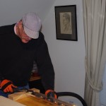
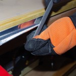
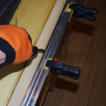
I spent some time this week going back to major parts of the vertical stabilizer and rudder to smooth the edges much better than my original efforts. Last week my technical advisor had shown me how edges should look. In retrospect a rather poor job had been done on final rounding my parts with the Scotchbrite wheel. Fortunately, none of these parts have been riveted together. The results now look much better.
The other activity this week was fabricating a rib doubler for the uppermost rib on the vertical stabilizer. I want to use 3/4″ plastic conduit obtained from Van’s to feed wire for either a VOR antenna, an anti-collision LED beacon, or both to the top of VS. The conduit can be held in-place with the appropriate sized hole drilled with a unibit. However this would weaken the spar web, so a doubler is needed. In addition, I wanted to use the #10 screw nut plate trick, ala the bonding straps, to allow for later installation of any electrical equipment.
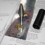 A scrap piece of sheet aluminum is measured out for the rib doubler. This picture shows the position of the nut plates, the unibit to be used for the 3/4″ hole and a practice piece of plastic conduit.
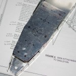 Here is the doubler rough cut for insertion into the upper VS rib.
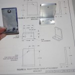
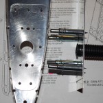 On the left is the fabricated doubler with all the holes drilled and deburred. I countersank the nut plate lobe holes for flush riveting with an ‘oops’ rivet. I wanted this to be flush for flexibility of later installations.
On the right is a practice piece with the plastic conduit inserted into the 3/4″ hole. As can be see here, the conduit has alternating bands of 3/4″ and 7/8″ diameter sections. This will allow the conduit to be threaded through the unibit hole and self-attach to the rib doubler. Nice and neat.
The lower VS ribs do not need this treatment, as special Panduit wire ties will be attached to the already present lightning holes.
