Category Archives: Rv-10 Build Project

Empennage Attach (2)

Use of paint booth and fabricate custom parts for empennage attach.

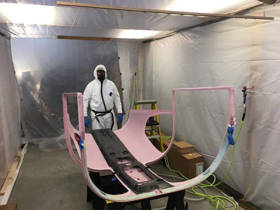
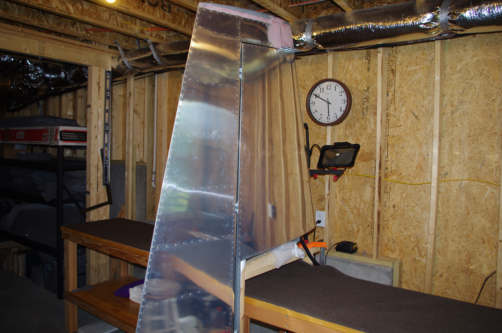
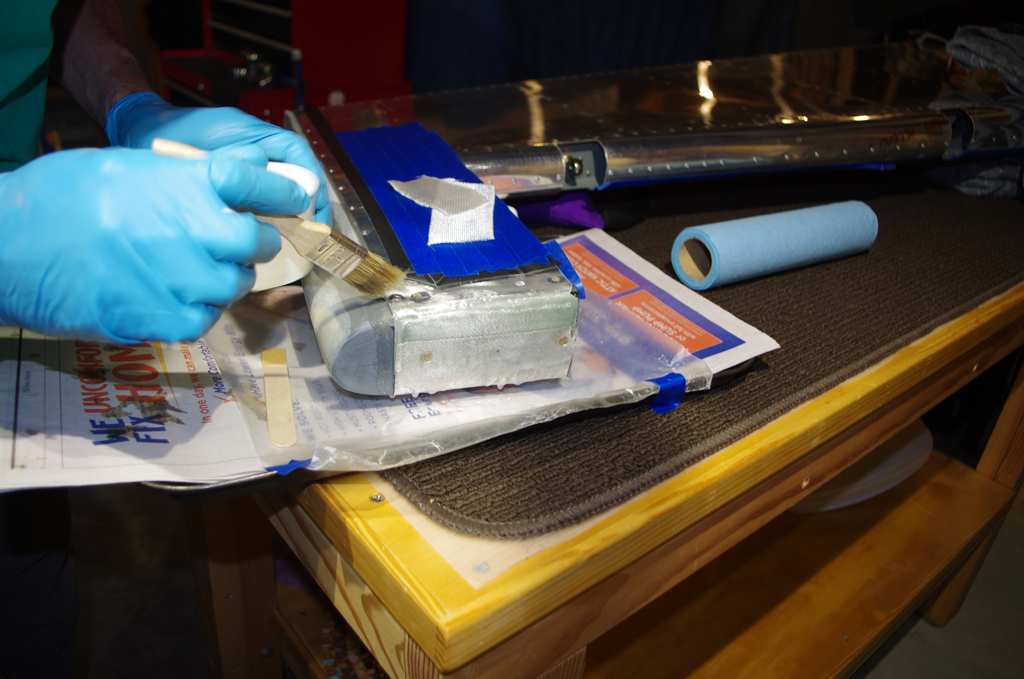
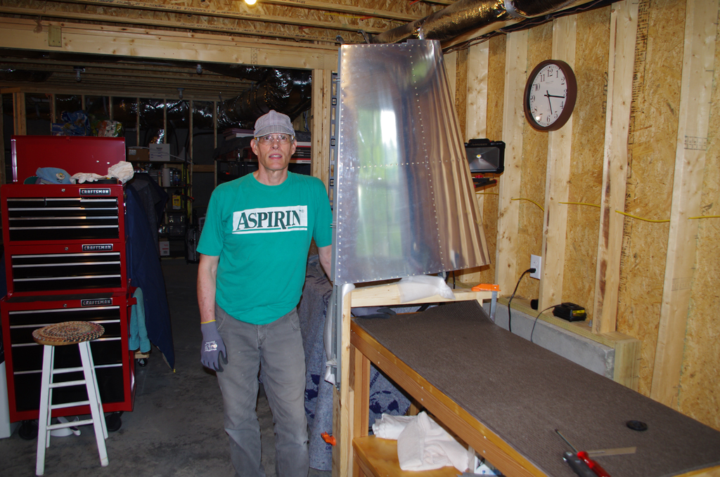
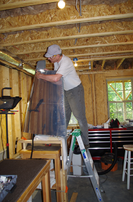
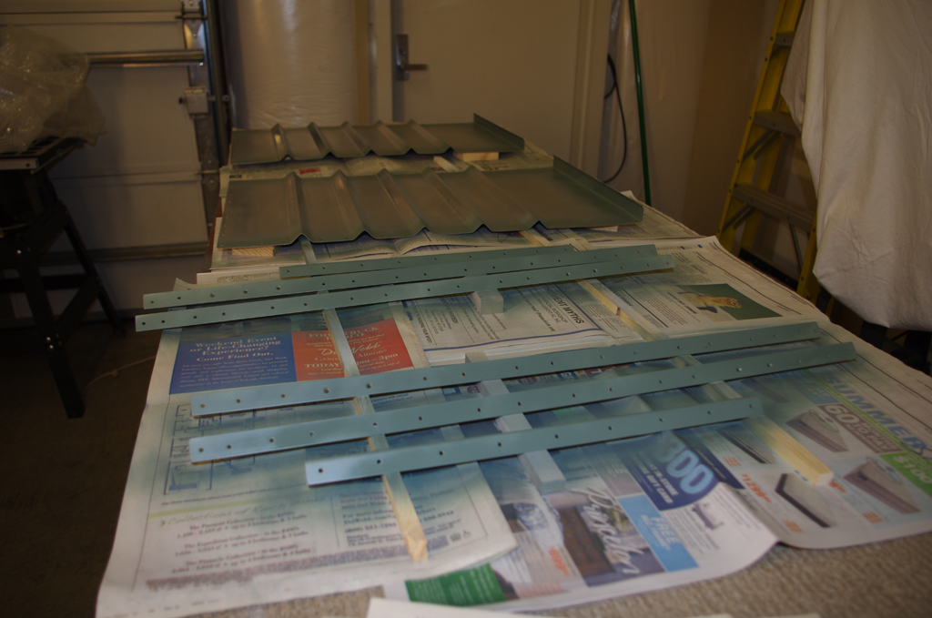
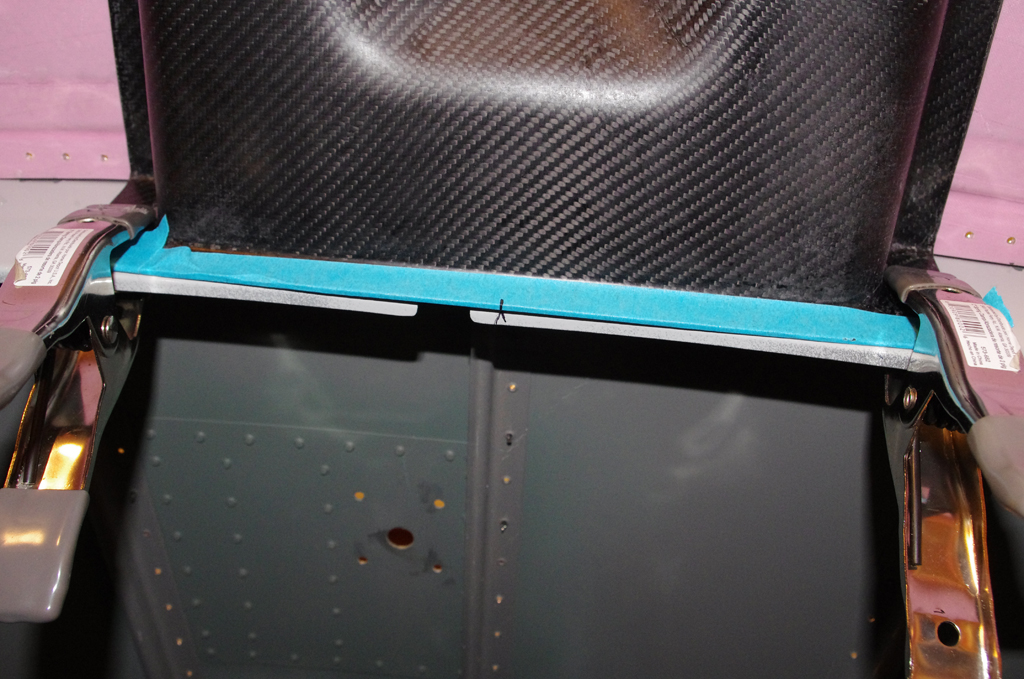
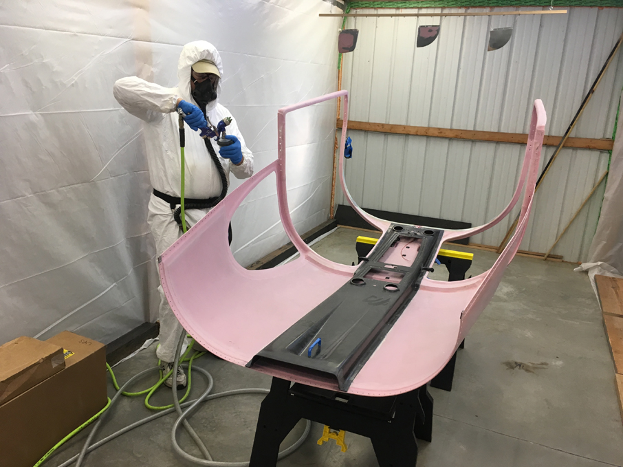
Over the last few months, Tal and I have been constructing a paint booth in his workshop.  This was our first run of priming parts in the just finished facility. Here he prepares to apply PPG DP40LF primer to the internal side of his canopy/overhead console, plus my horizontal and vertical stabilizer fiberglass tips.


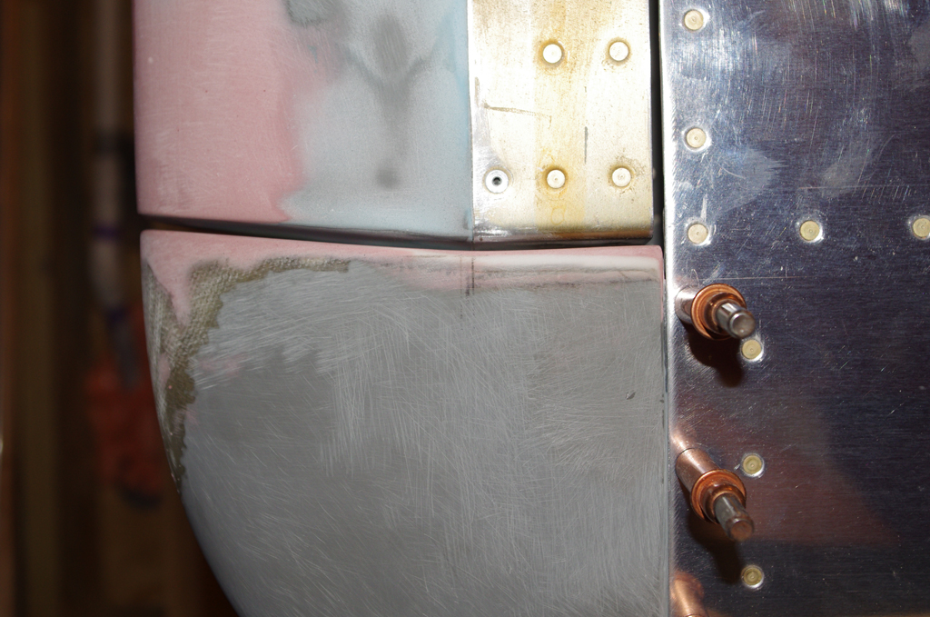
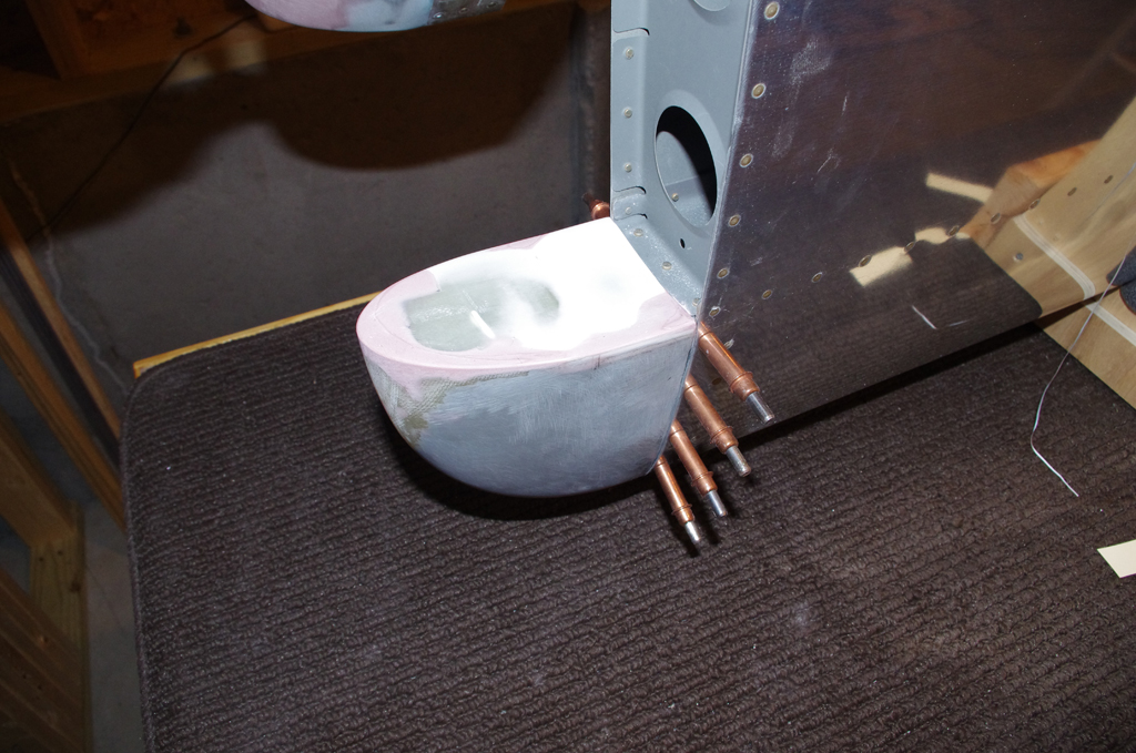
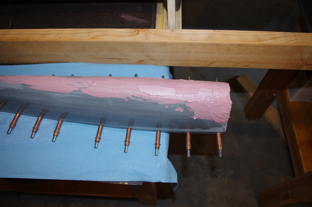
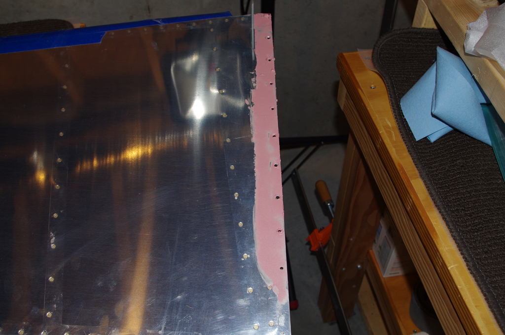
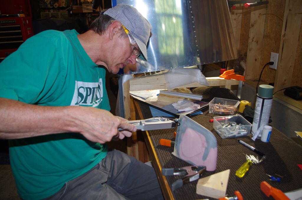
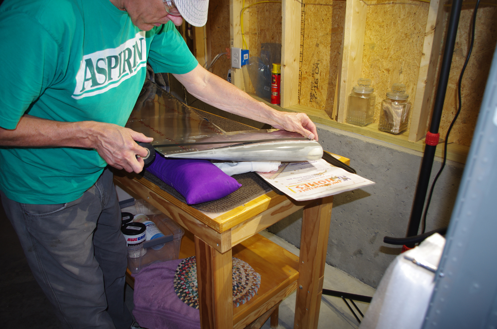
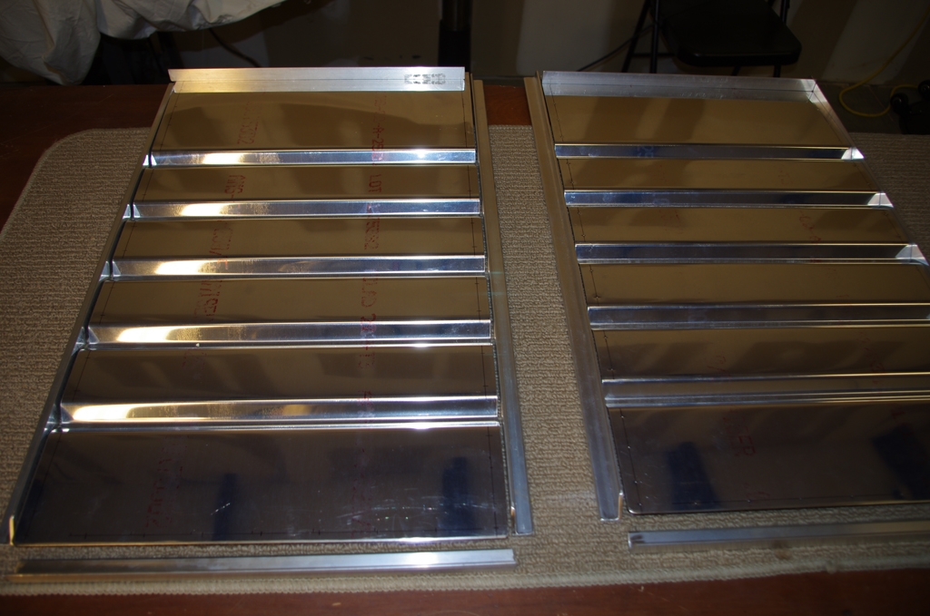
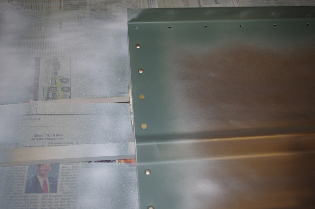
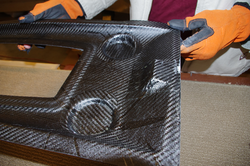
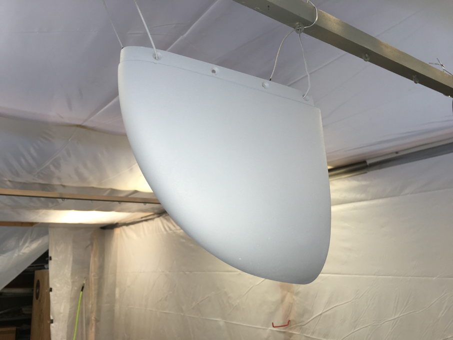
My tips had to be sanded heavily to get the properly rounded outside profiles to match the elevator tips.  My experience is the fiberglass parts from Van’s are just rough approximations – to get this right requires plenty  of work.  Witness the sanding completely through the gel coat on the left part, this required additional fiberglass/resin layers on the inside to prevent holes.


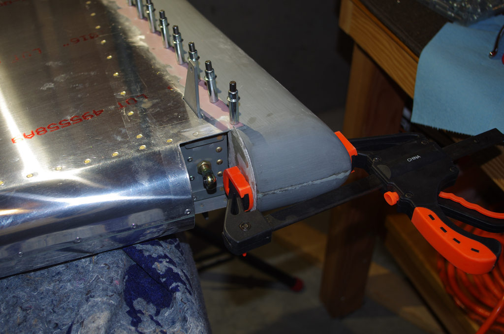
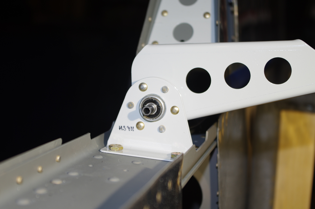
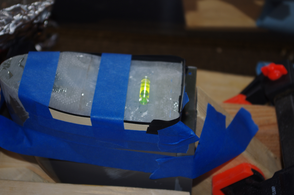
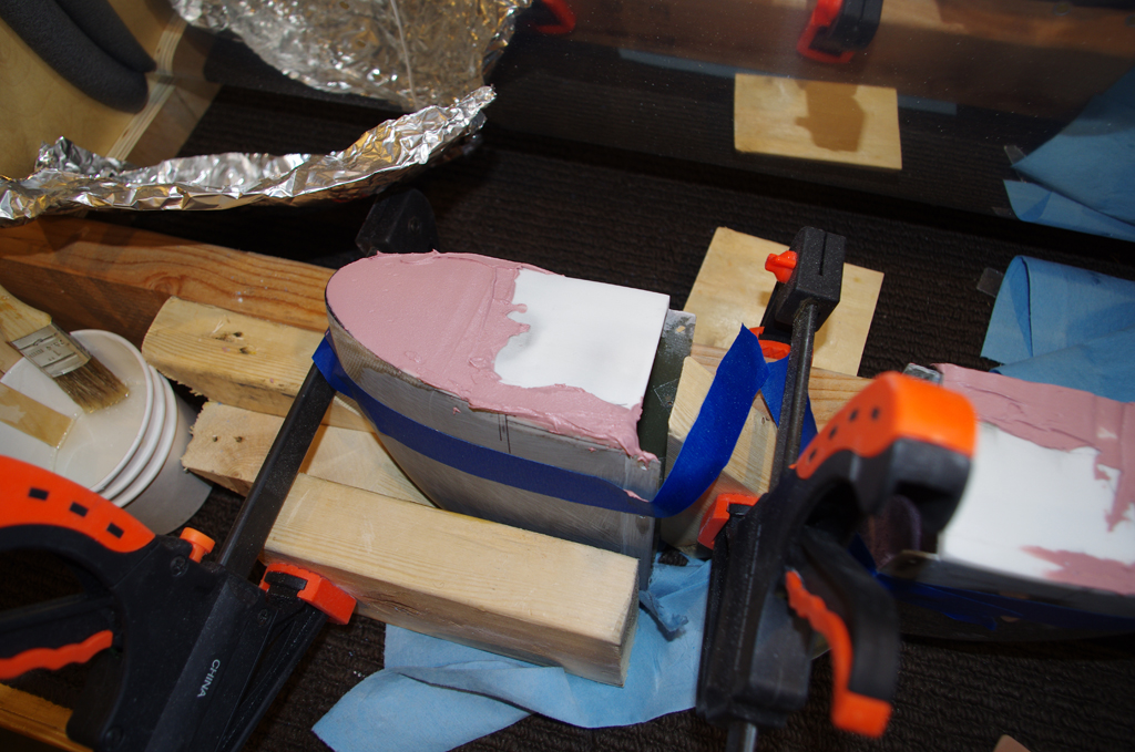
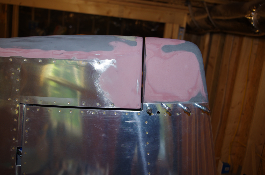
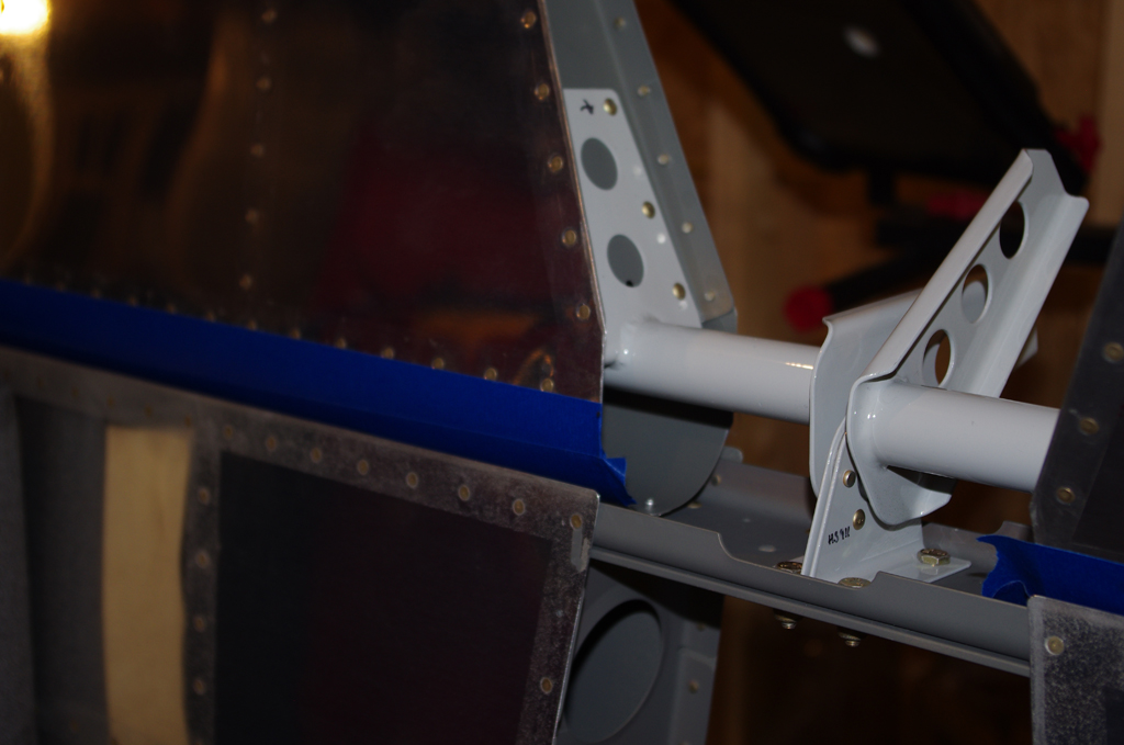
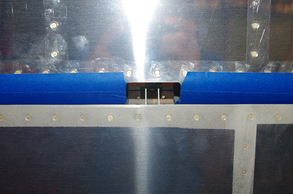
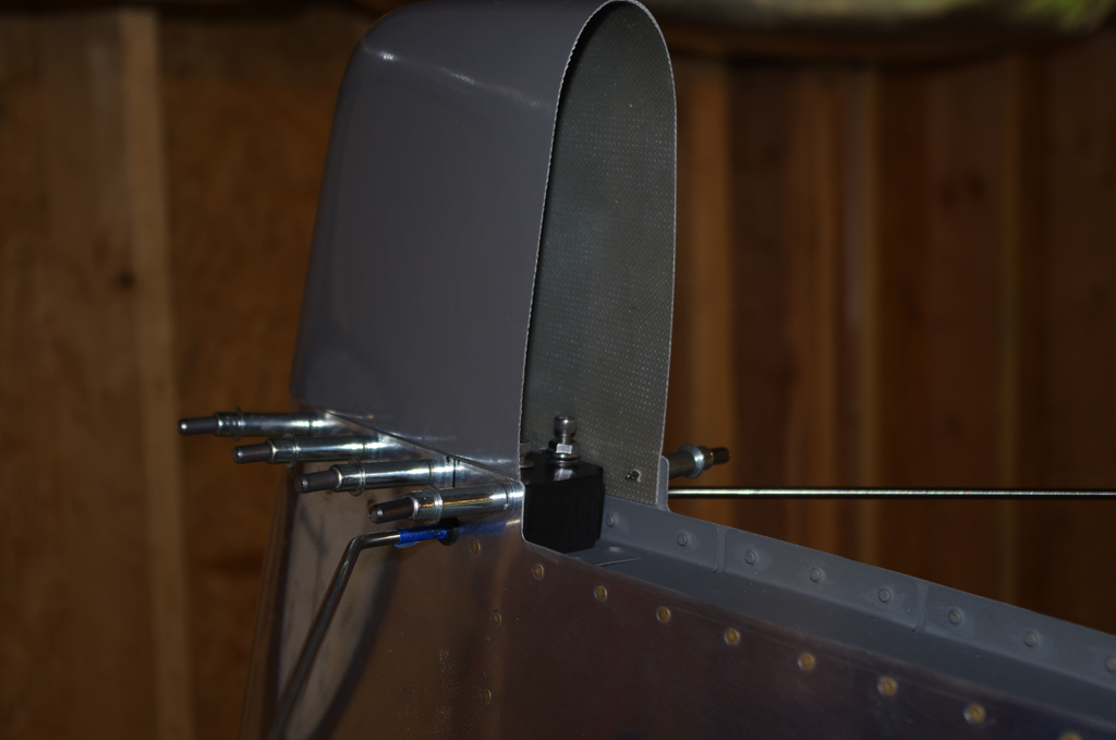
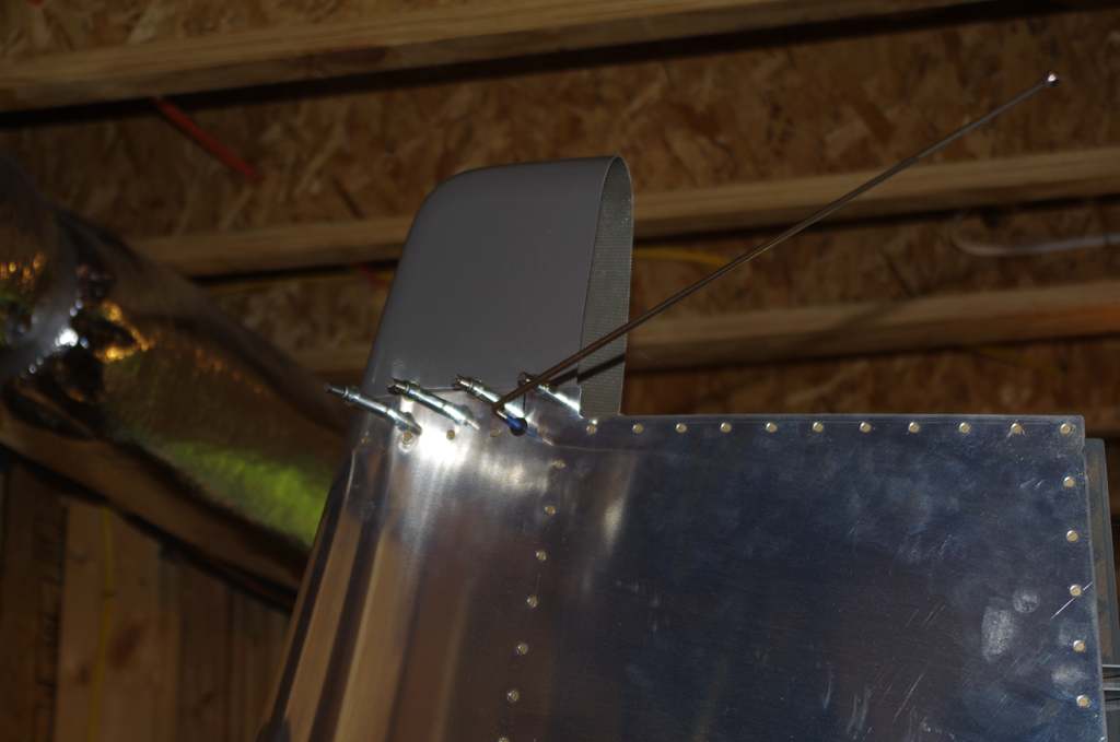
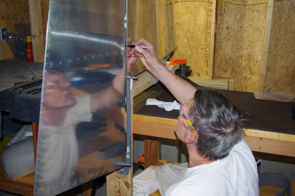
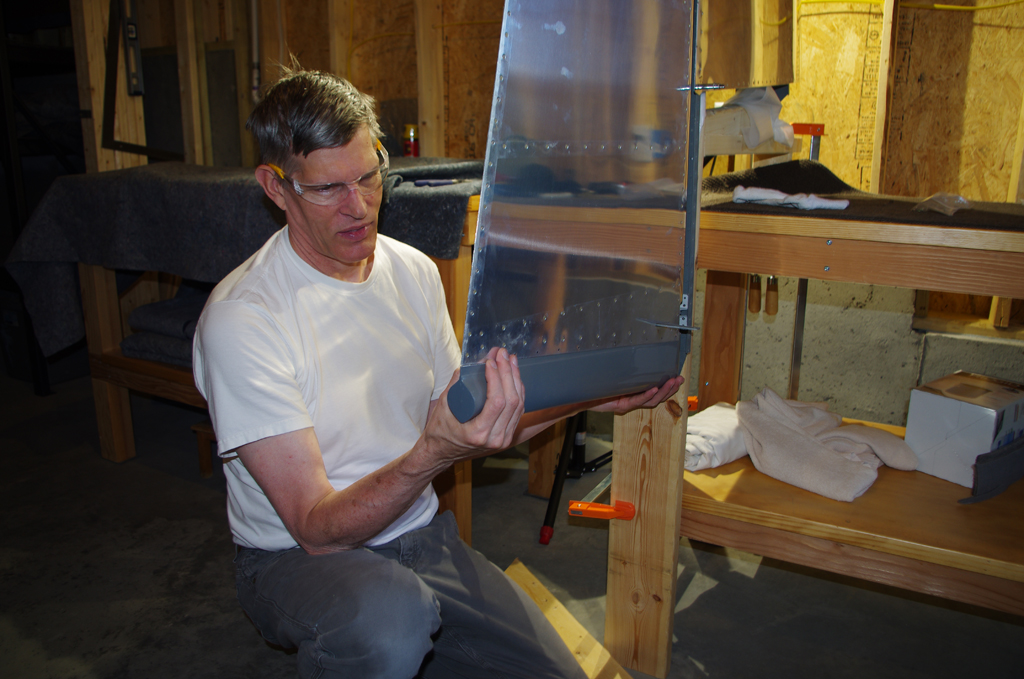
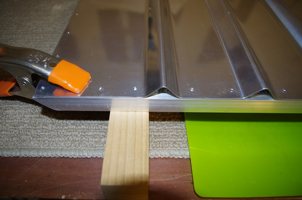
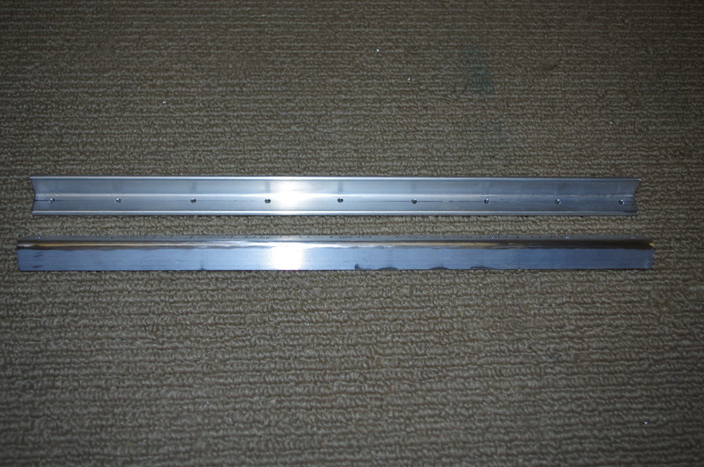
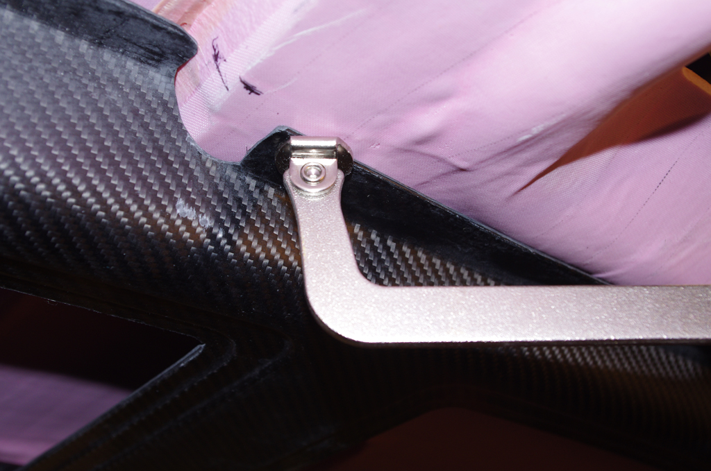
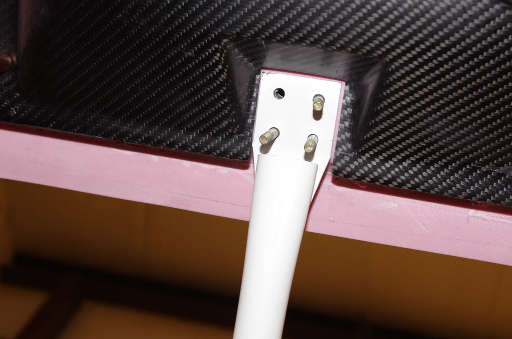
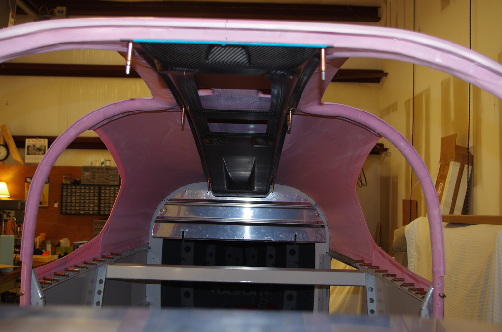
Next up is prepare and fabricate additional parts on the empennage attach sequence.  The left photo shows a supplimental cover on the rudder bottom.  Not necessary, but it should help deflect some water from entering.  The right photos shows HS attach shims being made.


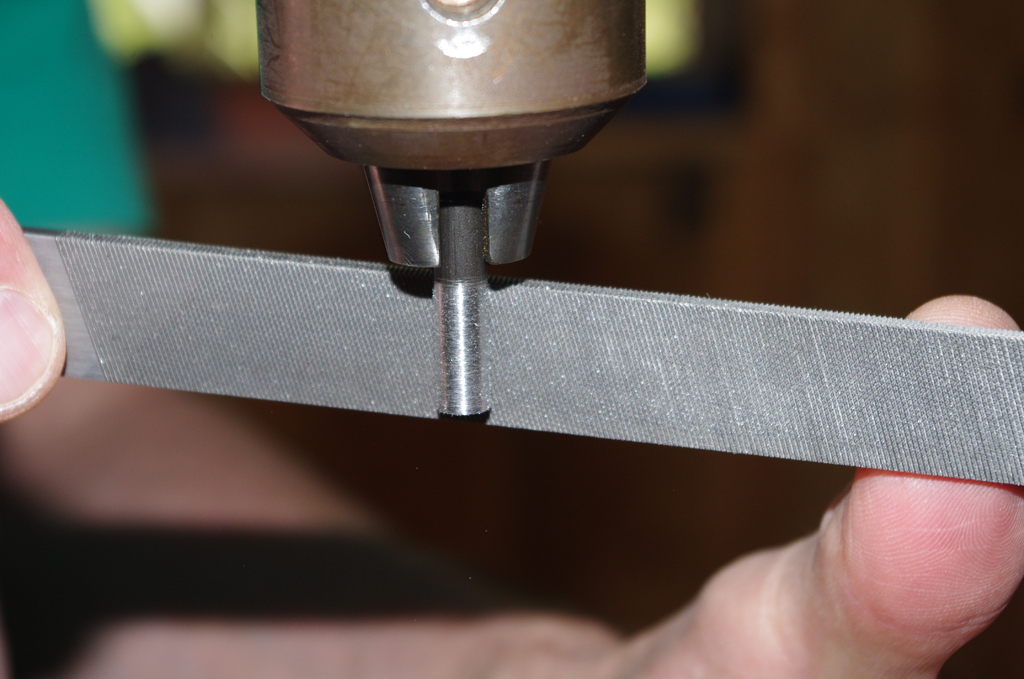
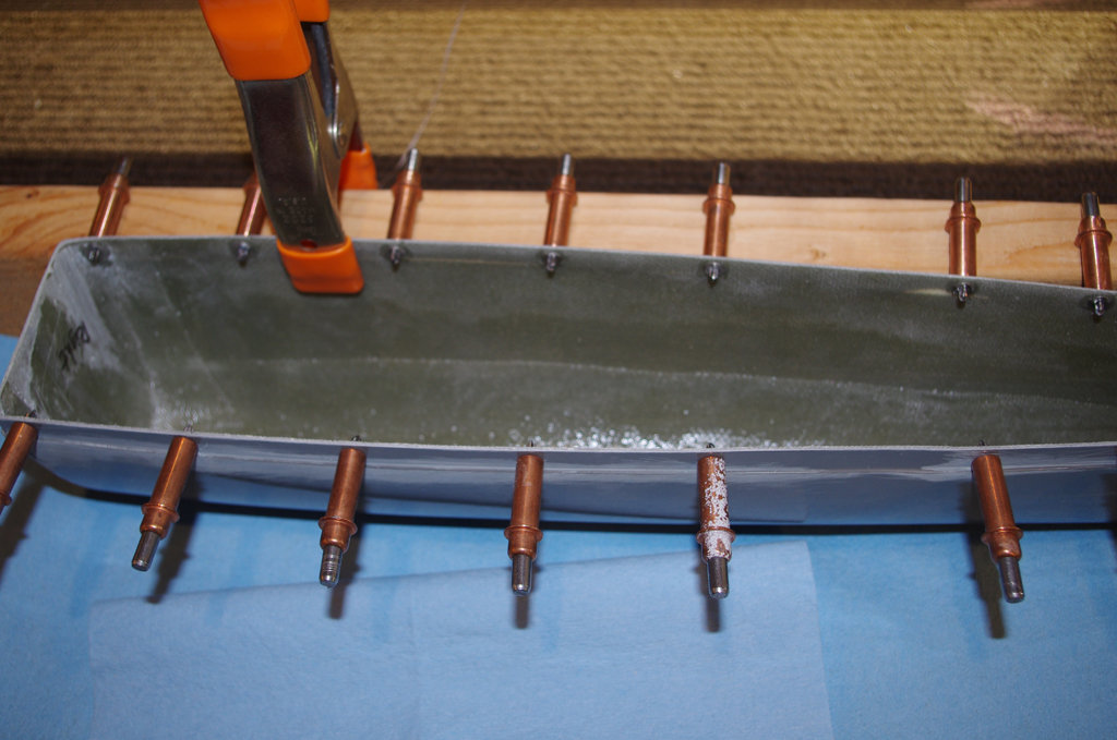
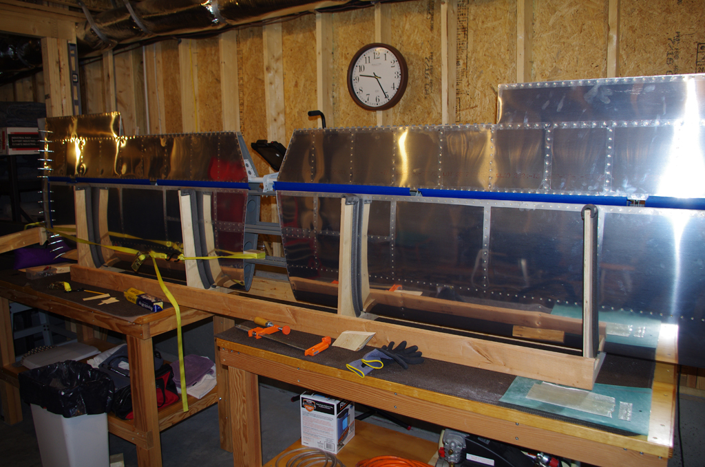
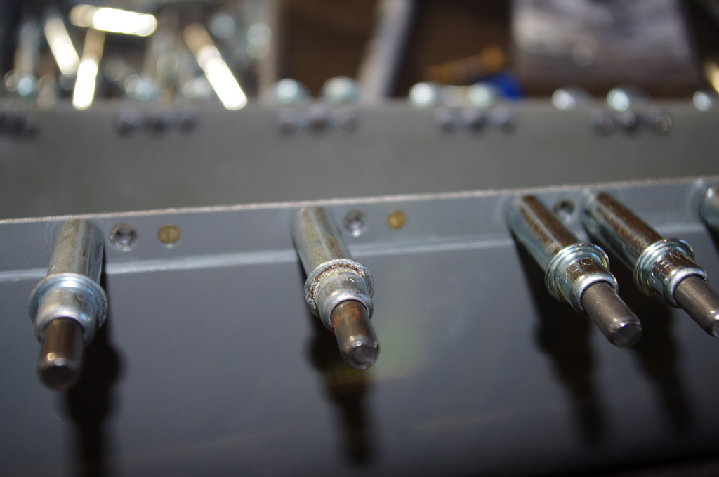
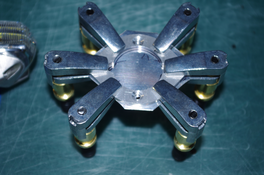
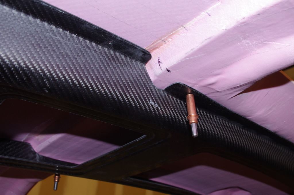
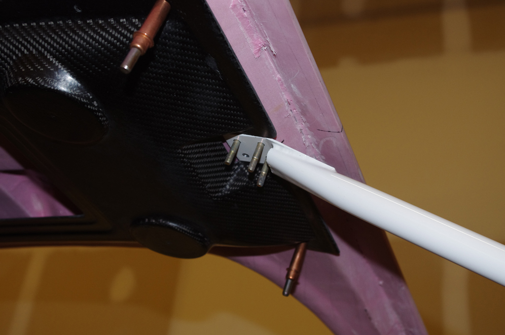
Attach points for the elevator trim motor and cables are being prepared on the left.  A 3/8″ spotting drill in a clamped vice ensures the attach rivet and bolt holes for the AN6 pivot bolts are correctly aligned to hold the trim bellcrank.


Empennage Attach (1)

While the horizontal stabilizer is in the jig for work on the fairings, there are also elements of control surface configuration which can be performed.  Checks on elevator up +30 degrees and down -25 degrees confirmed proper range of motion.  Then both sides are set to the “trail” position for drilling the elevator center bearing and elevator push rod bolt holes. To accomplish these tasks two drill guides were fabricated.

The first drill guide protects the center bearing while the pivot points in the elevator horns are configured.  The outer diameter of the guide needs to be reduced just small enough for a snug fit in the inner bearing.  The Delta drill press and Pferd files did the trick.  Once again I am amazed and happy at the incredibly small runout on the drill press!


The left photo shows the drill guide inserted into the center bearing for drilling the right elevator horn.  Next comes the actual drilling operation.  The right elevator is then removed and the same process used on the left elevator. The guide aligned everything perfectly and an AN4 bolt fits cleanly between both elevator horns.


To facilitate proper alignment of the push rod holes, a drill guide is made from a piece of oak sanded to the exact thickness spanning between the elevator horns. Caliper readings were used for initial hand sanding.  Then the piece is aligned and drilled perpendicular to the surfaces with the drill press.


Here the oak drill guide is clamped into place prior to drilling the second hole.  A piece of 3/16″ stainless rod is inserted to align the first hole for the right elevator with the undrilled face of the left elevator.  After drilling is completed, an AN3 bolt passes cleaning through both horns with perfect alignment.


This week was also some final sanding and fitting of the HS tips. The desired 1/8″ gap between the tips and the elevator fairings look good.


Empennage Fairings (6)

The tedious work of sanding, fitting, aligning, and build-up continue on the fiberglass tips for the elevator and horizontal stabilizer.  The nice part about fiberglass is you can add or subtract material as desired.  The down side is having to wait at least 24 hours between operations.

Here is a case of trying to level the HS tips, then fill as needed with resin/glass beads (white) or Awl Grip fairing compound (pink).  The same operations apply to the elevatore tips.  Sand, fit, fill, rinse, repeat…


The left shows backing washers clecoed for superglue attachment to the elevator tips. These are not required, as these holes are supposed to be countersunk, then pop riveted onto the elevator.  However, experience has shown the fiberglass gets very thin after the countersink operation, so this attempt should reinforce the connection.


… and while waiting for the next round 0f build-up to cure, I started adding the nutplates to the horizontal stabilizer.  Eventually these will fasten a custom fairing which sits between the horizontal and vertical stabilizers.

Empennage Fairings (5)

Work on the vertical stabilizer and rudder fairings was recently completed – at least for the time being and until final preparations for paint are underway.

My overall satisfaction level is good with the overall fit, gaps and blending of skins to fairings.


The upper and lower elements are clecoed in position to check the final rudder angles, gap tolerance on the upper rudder swing and rudder/vs skin clearance.  All within tolerance and acceptable for now.


The next fairings to be addressed are on the horizontal stabilizer.  To properly fit these, Section 11 Tailcone Attach elements must first be completed.  The elevators are fastened to the rod end bearings of the HS, then angles and clearances checked for free movement.

adfa


Here the HS cradles in the jig built many moons ago with the original construction.  The elevators are in position to begin work on the fairing alignment.


Close-ups of the gap between elevator tips and horizontal stabilizer, then the rod end bearding and the hinges.


Initial fiberglass filling of the HS end caps after rough trimming to shape with the elevator tips.  These are not straight – bending backwards at an 8degree angle. This is enough to  prevent the fiberglass molding from being simple.


Empennage Fairings (4)

More sanding, fitting and filler on the fiberglass parts. Plus the addition of nut plates at various locations to complete some of the parts.

This photo shows the lower rudder fairing with #6 nut plates soft riveted into place. I made this fairing removable, as the AeroLED Suntail nav/strobe light wiring and electonics still needs to be added. A machined spacer from Cleaveland Tools provides a stable surface for fastening the Suntail afterwards.


Final filler and smoothing on the bottom rudder skins.  These parts hold the bottom fairing.


Nut plates for #6 screws are also install on the vertical stabilizer top.  These will allow removal of the top to access the VOR bracket made earlier.


The bottom of the vertical stabilizer skins also takes #6 nut plates.  These holes will later be used to fasten the fairing which bridges  between the vertical and horizontal stabilizers.


Empennage Fairings (3)

This week was about sanding and fitting the rudder top and bottom fairings.

This shows the top fairing pop-riveted into position on the rudder.  The end cap with the lead counter-weight needed some additional material to match well with the VS top.


Plastic electrical tape is applied to keep the resin off unwanted parts.  Then the end cap is sanded and cleaned for fiberglass layers.  These are probably not necessary, but I wanted to ensure the overlapping metal parts are held rigidly in place (should help prevent cracking along the seam)


Multiple layers of fiberglass and resin are applied. Because the resin is quite fluid at the start, some droops down the lower face.  This will later be sanded smooth and covered with Awl Grip D8200 for the final finish.


The basement shop was also enhanced with a new single stage, 12.8cfm air compressor made in USA by Quincy. Next steps are get the electrician to wire a dedicated circuit, then fire up for plane building usage.

Empennage Fairings (2)

Further fitting the VS top and rudder bottom fairing were the activity for this week.


The VS top fairing did not fit properly in the metal opening.  Throughout this build I have found all the fiberglass parts to only be approximations, much work on proper alignment and sizing has been needed.   Here the rear profile is being sanded to shape and the back panel straightened to match the rudder top fairing.


The AeroLED Suntail NAV/strobe will be attached to the lower rudder fairing via a machined aluminum spacer purchased from Cleaveland Tool.  The fiberglass from the fairing at this point is fairly thin, so fabricating a backing plate for the six pull rivets was chosen. This photo shows interim progress.

Empennage Fairings (1)

After months of inactivity due to the new house move I am finally back to working on plane parts.

Moving day!  Here are photos for relocating many plane parts from the rented storage unit to my new basement workshop.  Outside temperatures this time of year are in the mid-90’s.  The basement has a dehumidifier with temperatures in the low-70s, humidity around 40% – perfect working conditions.


First action in the new shop was build a jig for the vertical stabilizer and bolt down to the workbenches.


The fiberglass part needs to cover the NAV antenna holder with enough space for easy assembly. These show the initial fitting, plus the bend antenna rods in position.  Nice.


Eric helps install the rudder linkages, then rough fit to the vertical stabilizer.  This was a provisional attachment to check fit/finish. Adjustments to the flex angles and VS skins are needed.


Fiberglass caps on the rudder top and bottom are next on the TO_DO list, plus finish filling the VS cap piece.

Rear Seat Backs

The work on these seat backs seems simple compared to some recent activities, but nevertheless takes time to do right.

Typically I cut the parts, debur and scotchbrite, then layout before further processing.


Fastening holes are measured on the rear seat back corrugated material, then #30 match drilled with angle brackets.


Upper and lower angles are measured and #30 holes fabricated with the drill press. These become the template for holes in the corrugated material.


The upper angles needed to be rounded on the inside for a tight, nesting fit with the rear seat back.  The bench sander and scotchbrite wheel were used to provide the relief. After dimpling and countersinking as specified the areas joined together are self-etch primed.


The alligator-jaw pneumatic squeezer is used to rivet the parts together.


The almost finished seat backs are test fit for lower hinge alignment, then riveted together.  Last step is a light coat of sandable primer. Eventually they will be painted the same Boeing 707 grey as the rest of the interior.

Overhead Console (1)

The Christmas vacation provided opportunity for some significant shop time.  The main focus for the 10 days off was fitting the overhead console and fabricating the rear seat backs.

The carbon fiber console was obtained from AeroSport Products. It is very light weight, but not exactly proportioned to the Van’s cabin cover.


The middle portion needs to be relieved to accommodate the heavy fiberglass reinforcement section of the cabin cover.  This element apparently is very significant to the structural integrity of the plane and everyone suggests no alterations to this element should be undertaken.  My intention is feather the console into the ceiling with fiberglass and paint (no need for the carbon fiber look).


Here are photos of aligning the rear console with the baggage bulkhead.


A #30 drill with a drill stop set to a depth of about 1/4″ was used to drill through the carbon fiber and the under layer of fiberglass/resin of the cabin cover – just enough for a cleco to grab. Drilling much further would penetrate the outer fiberglass, definitely not recommended.


The console was removed and modified for the center bracket, then refit to check clearance.


Here the console is shown in final fit configuration.  Further work on vents, lights and cabling will be performed with the cabin off the plane.  With the canopy upside-down gravity will assist holding the console in-place.