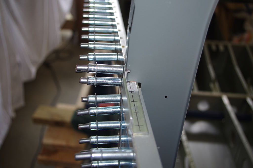
Next steps in the tailcone attachment were final riveting of the side and bottom skins to the fuselage.
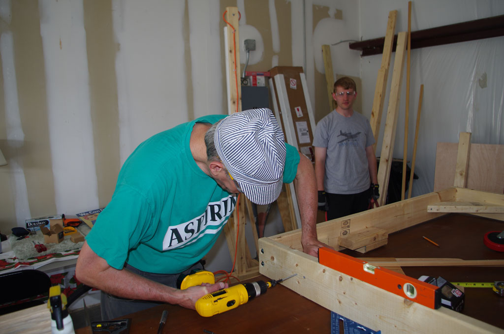
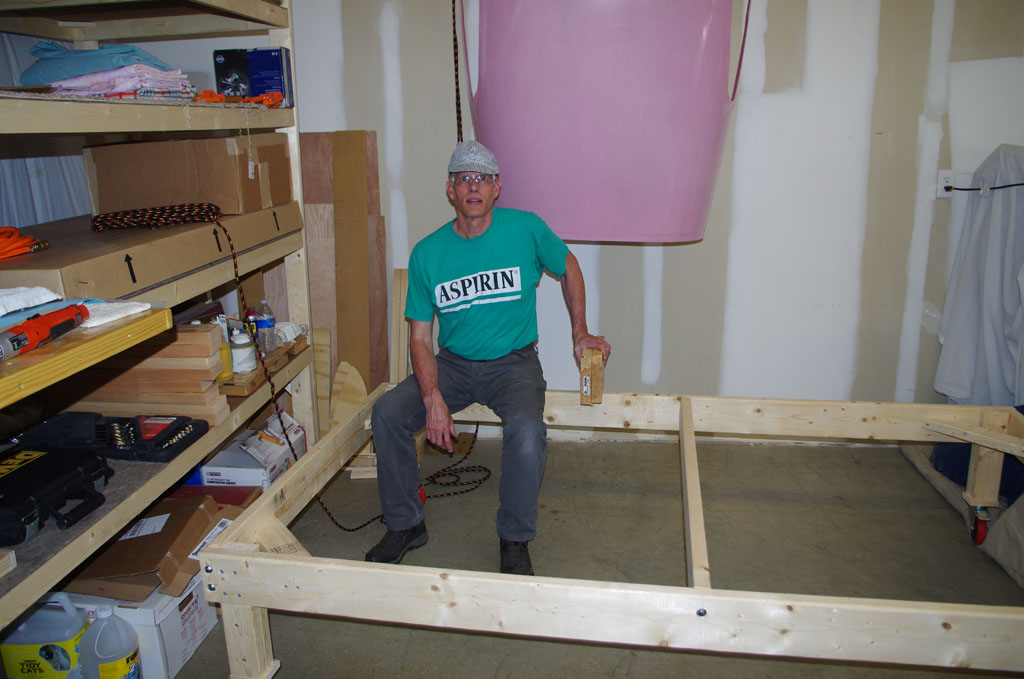
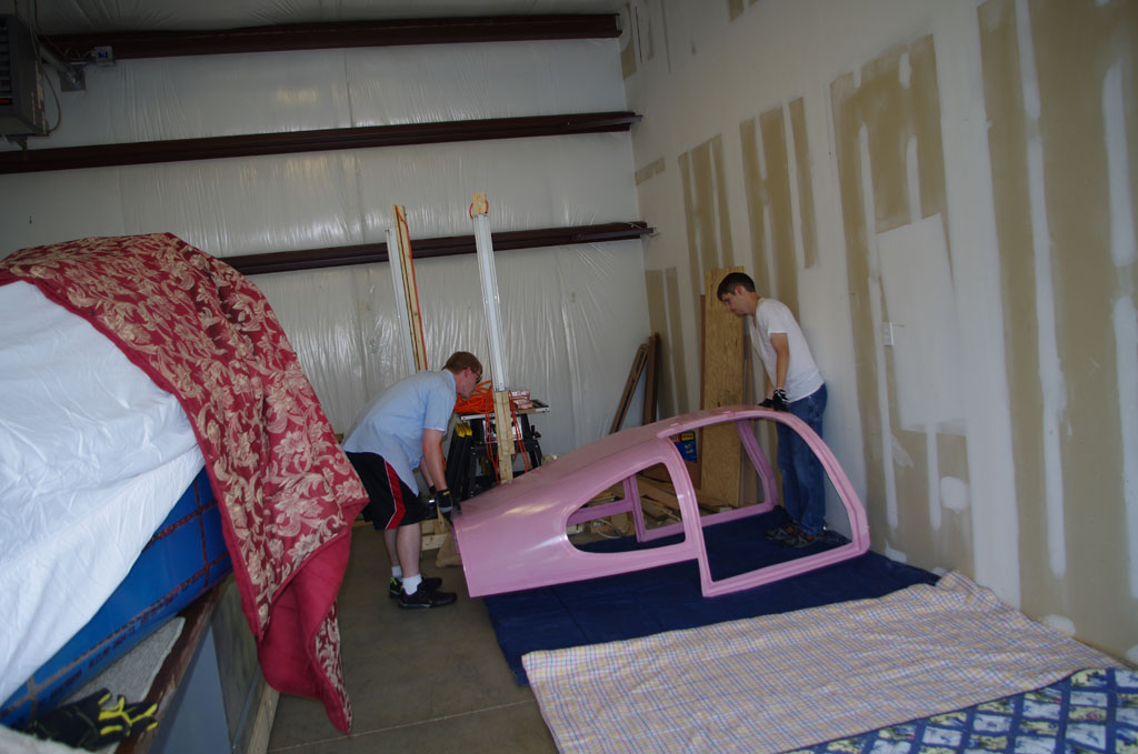
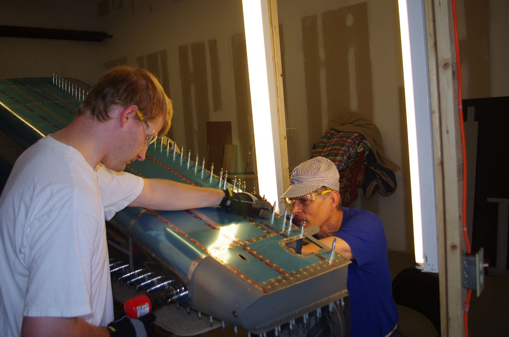
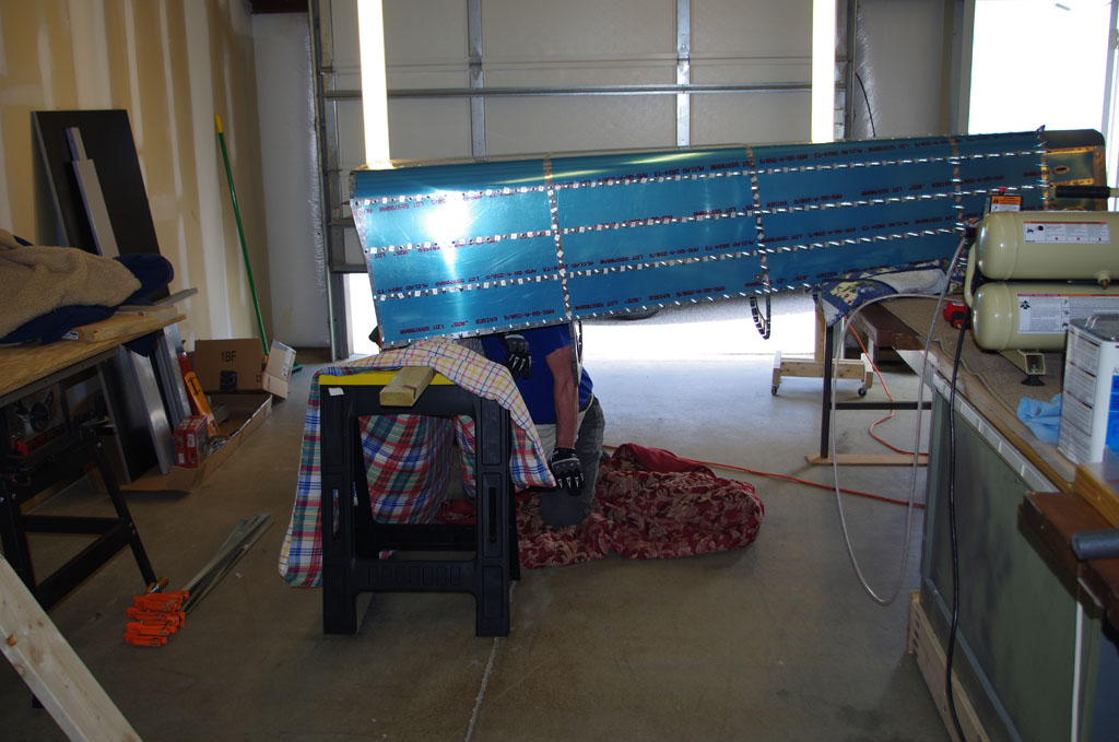
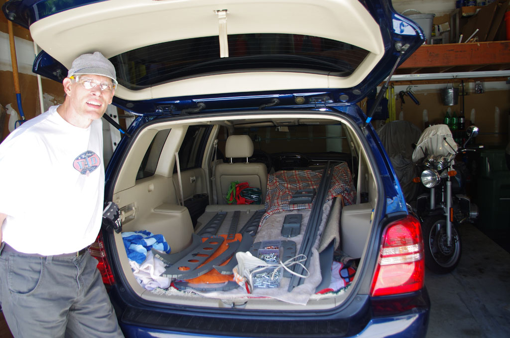
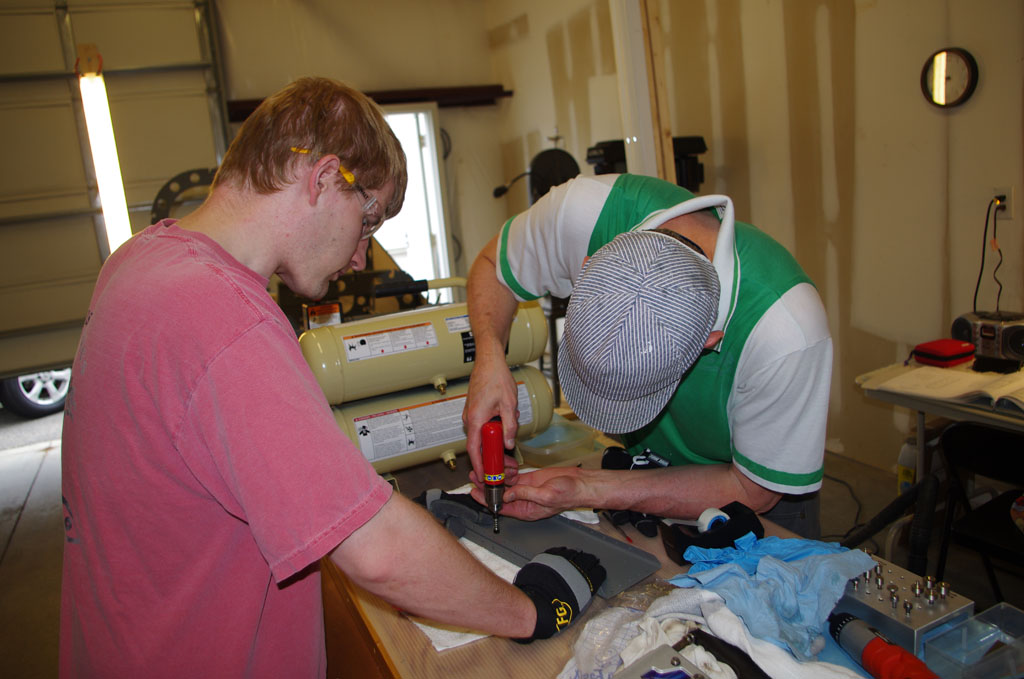
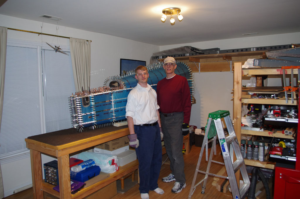
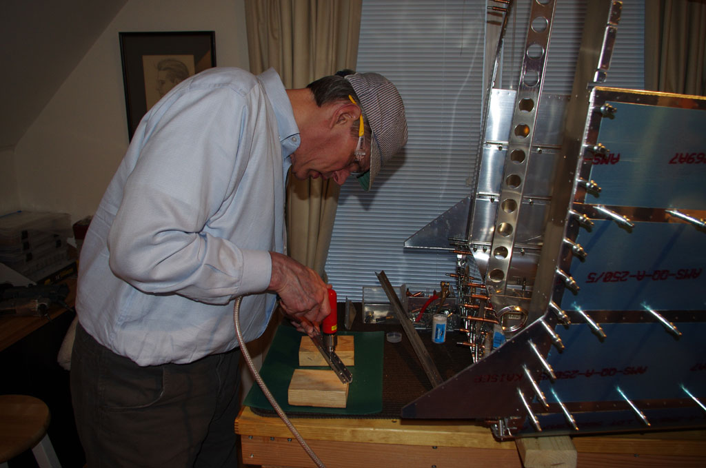
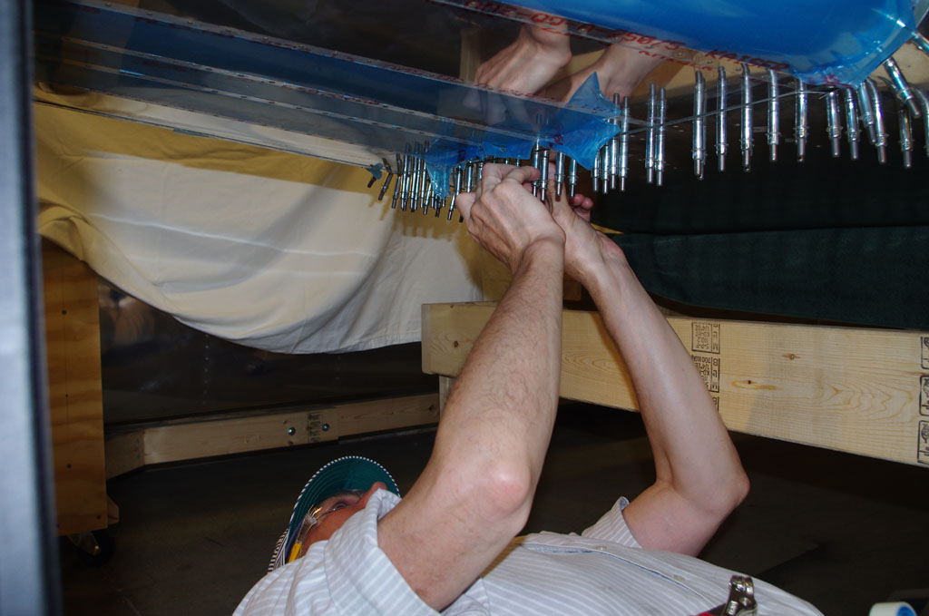 Eric bought a creeper for rolling under the fuselage jig. This came in very handy for placing rivets before driving. For sedentary office workers like me, reaching up for a few hours leads to weary arms. So Eric and I traded off on the process. I cleared the holes as needed, deburred the outer skins one more time, then taped the appropriately sized rivets in place for driving.
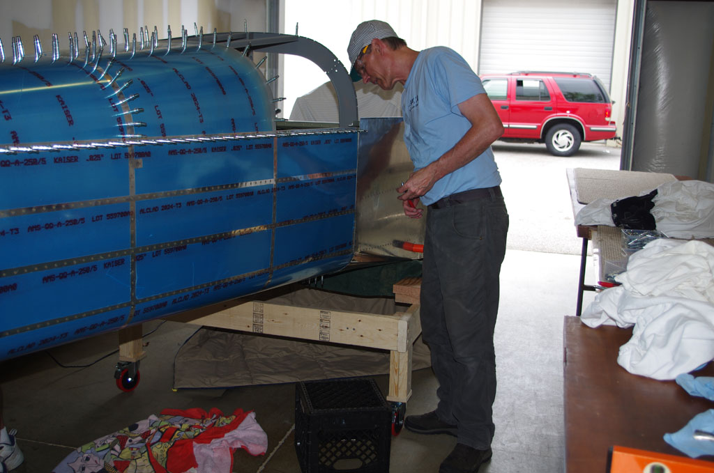
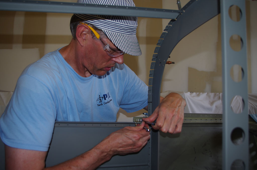
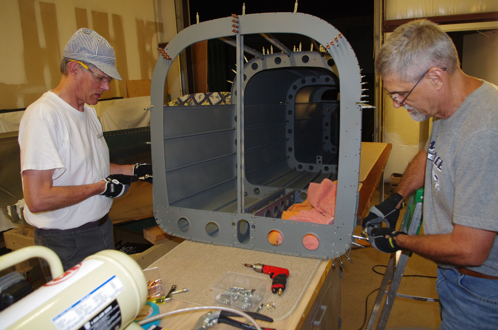
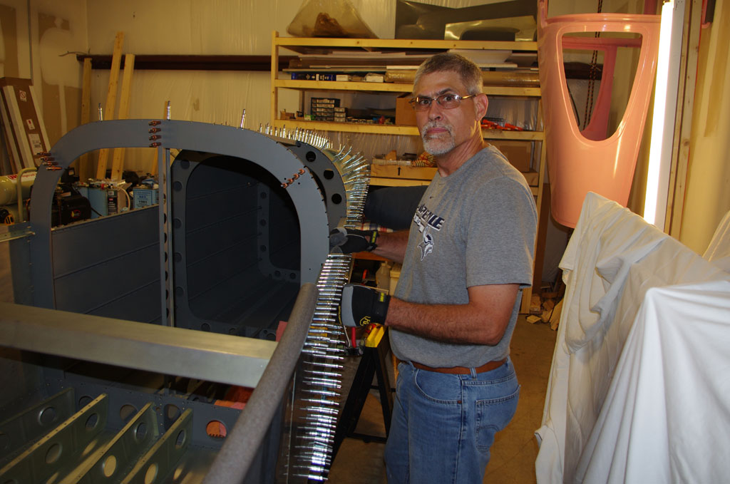
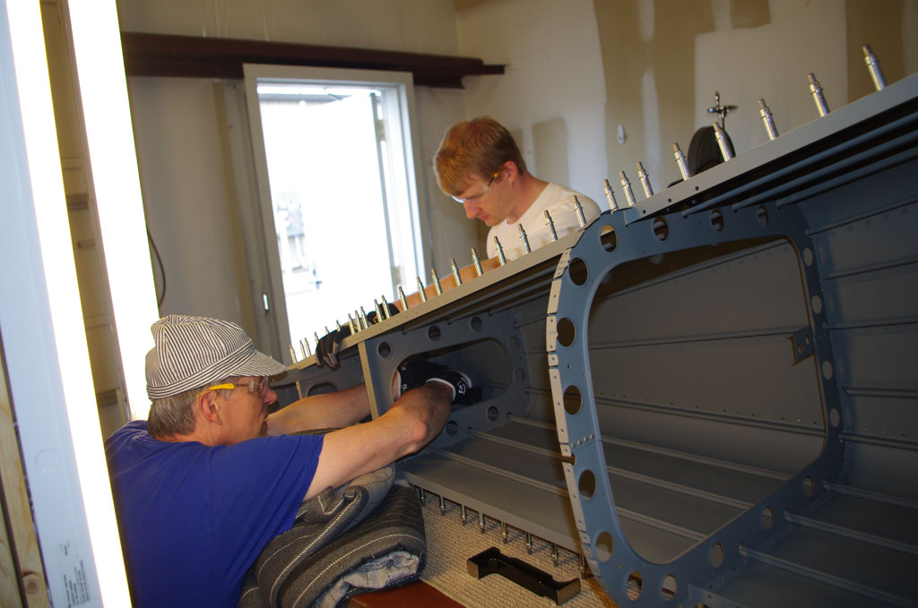
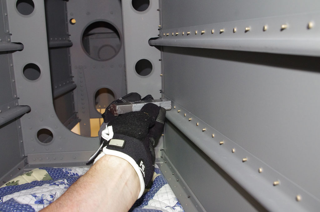
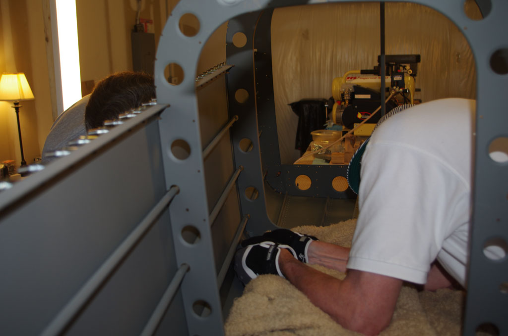
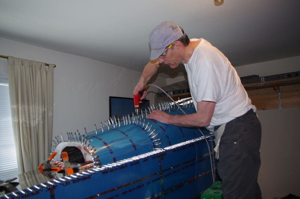
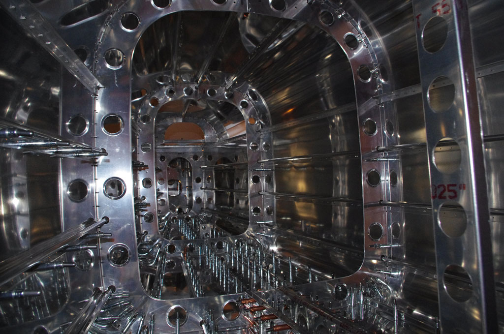
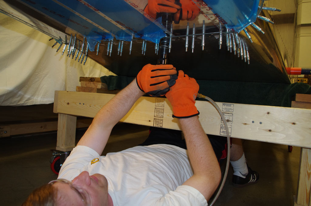 Here Eric drives the lower skins rivets, while I buck them inside the plane.
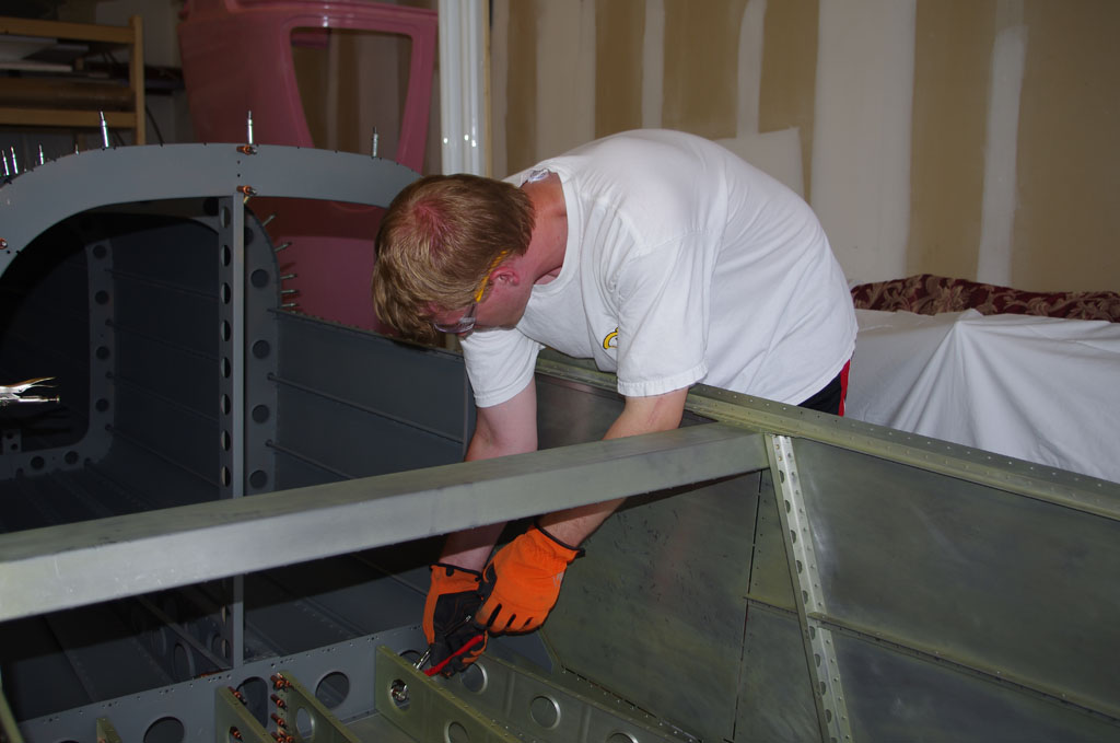
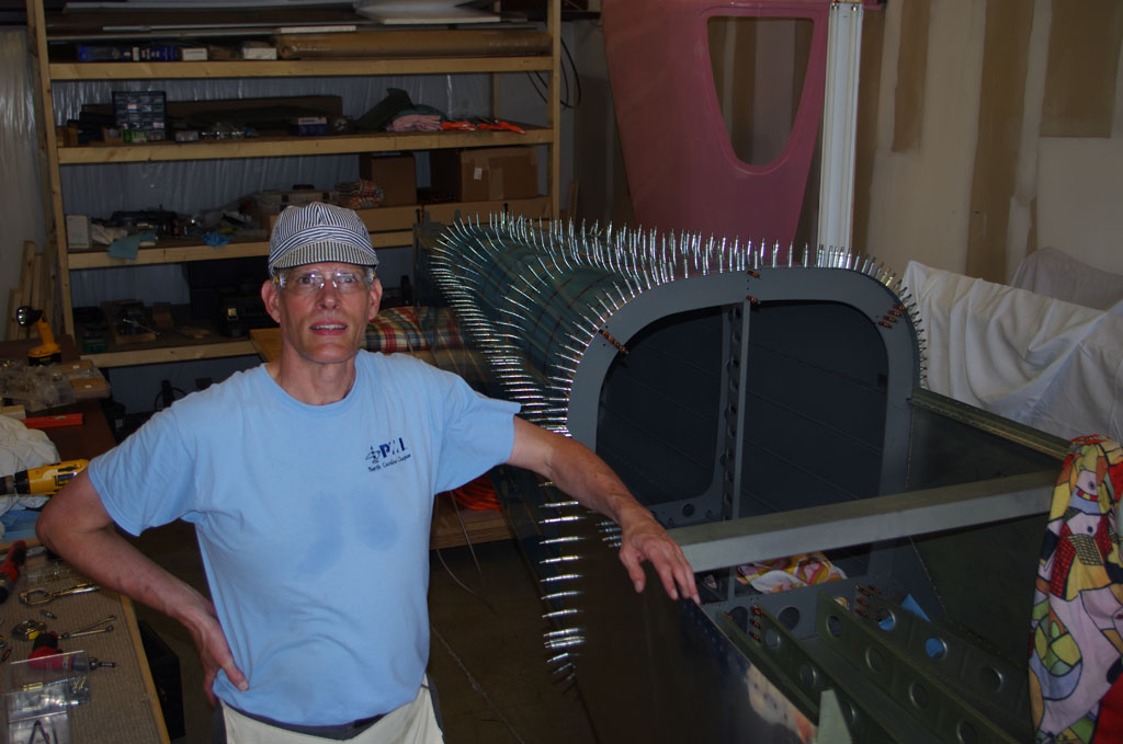
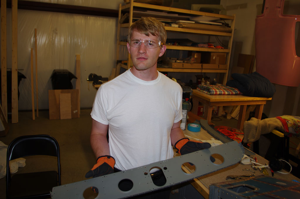
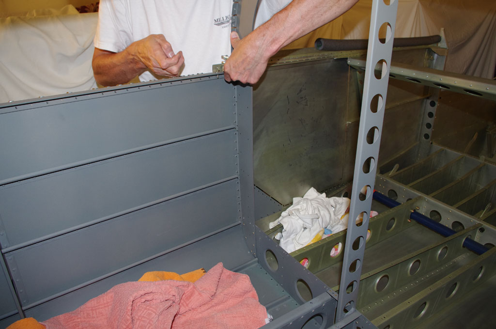
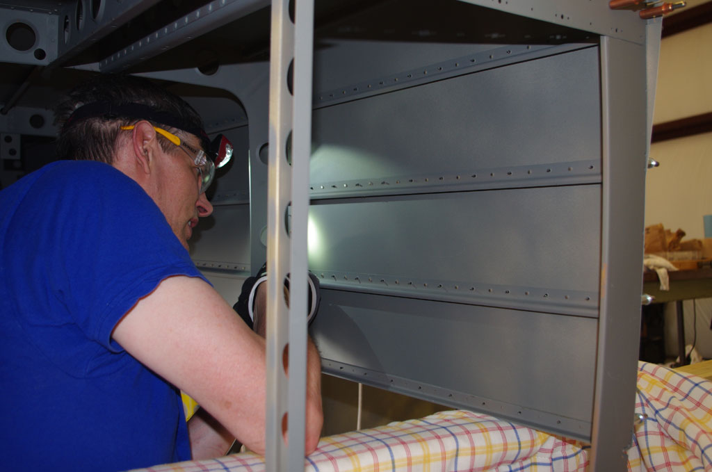
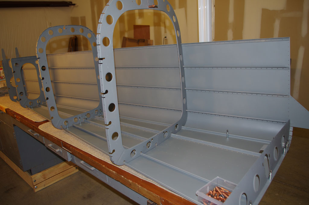
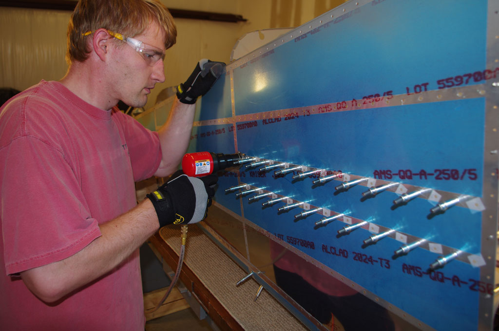
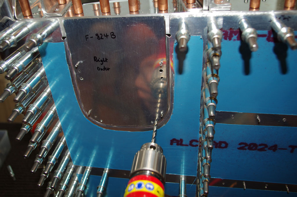
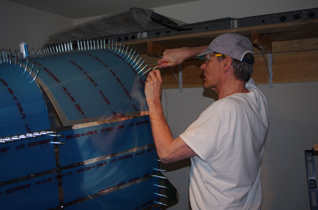
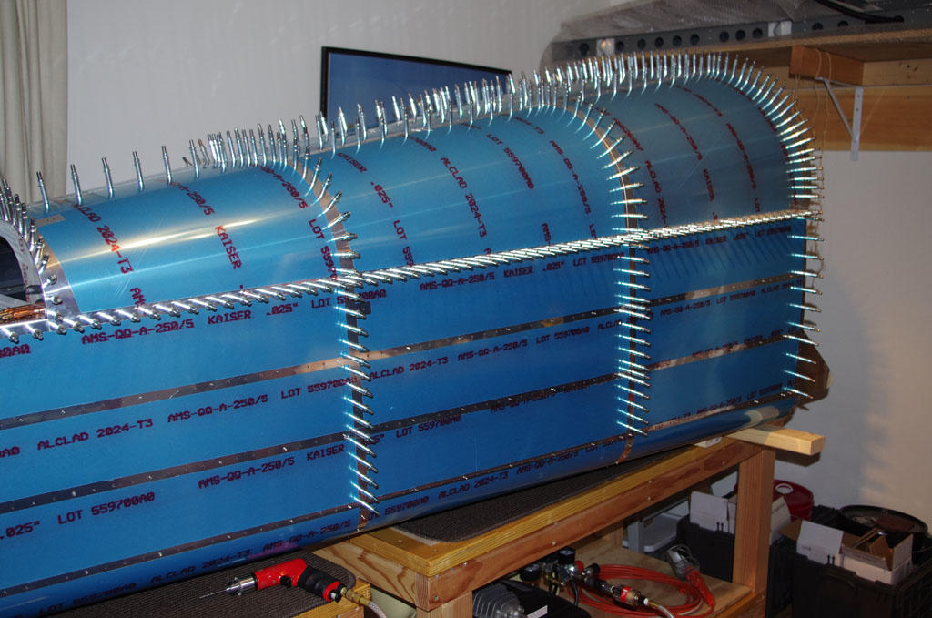
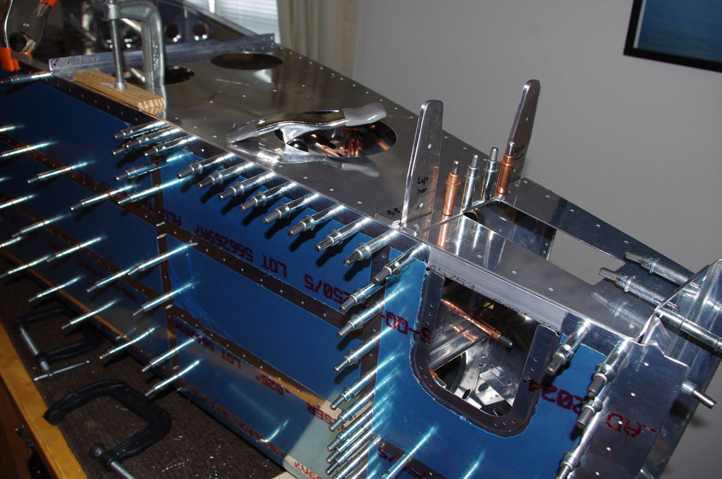
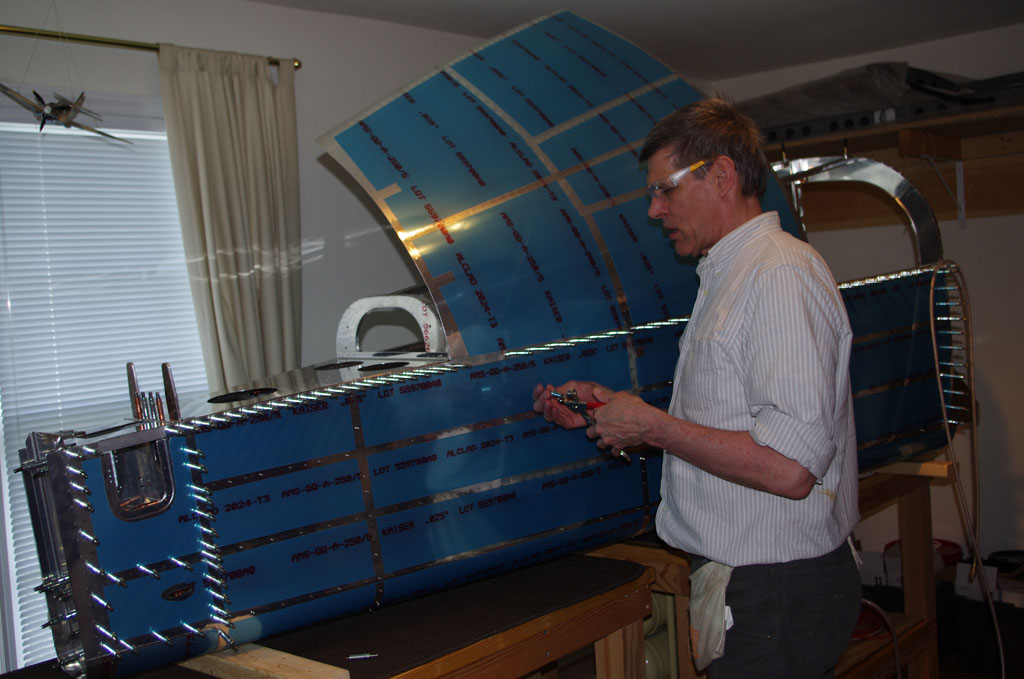
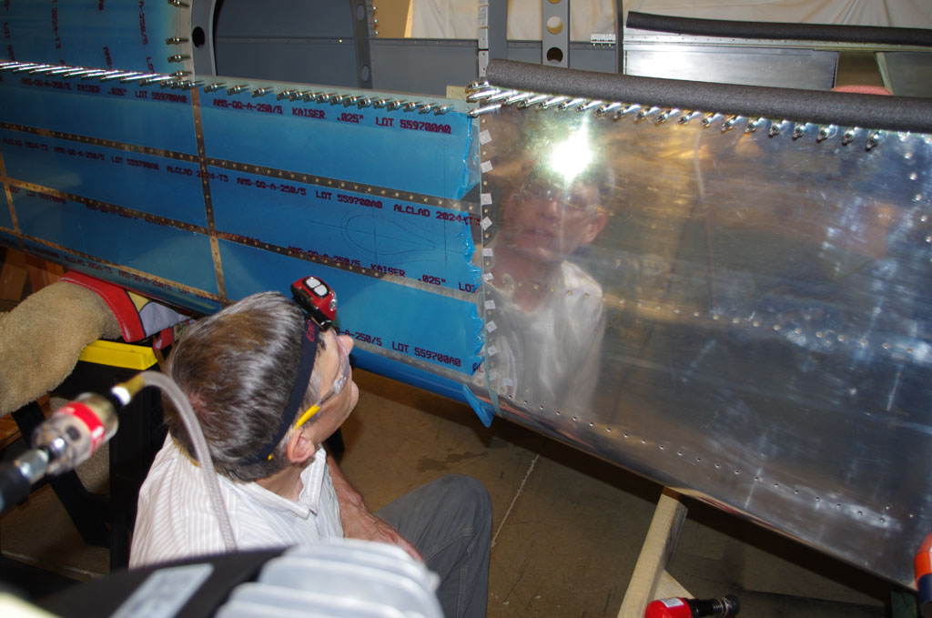 Admiring the right side handiwork prior to setting the last set between the baggage bulkhead and the fore/aft skin overlap.
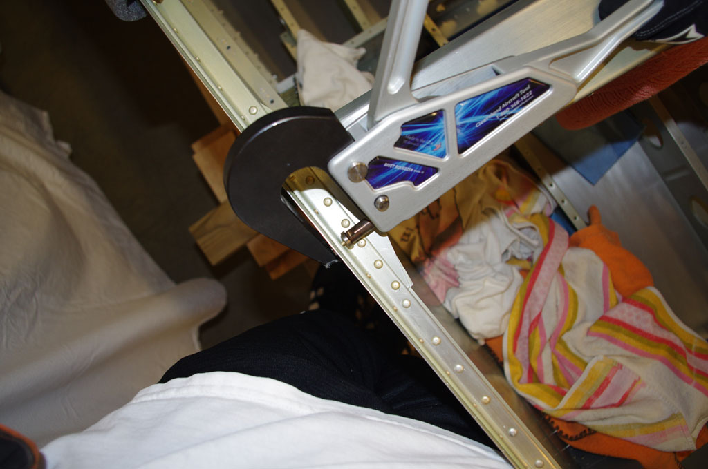
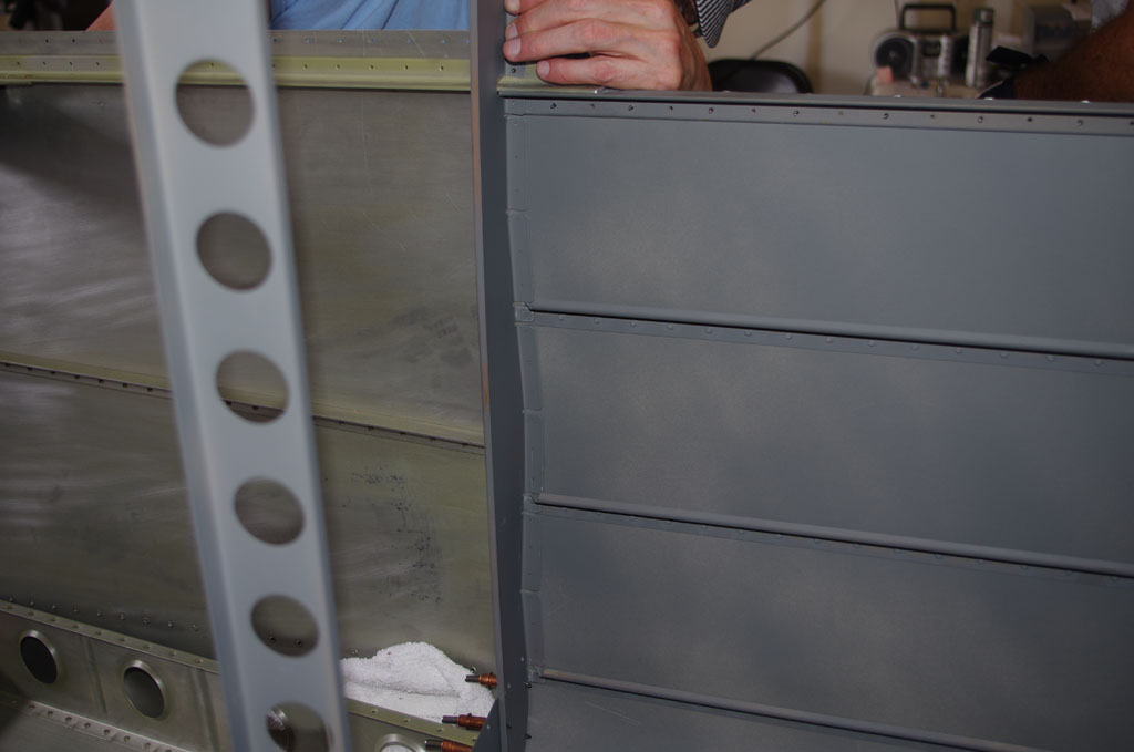
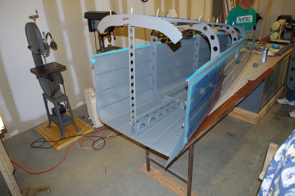
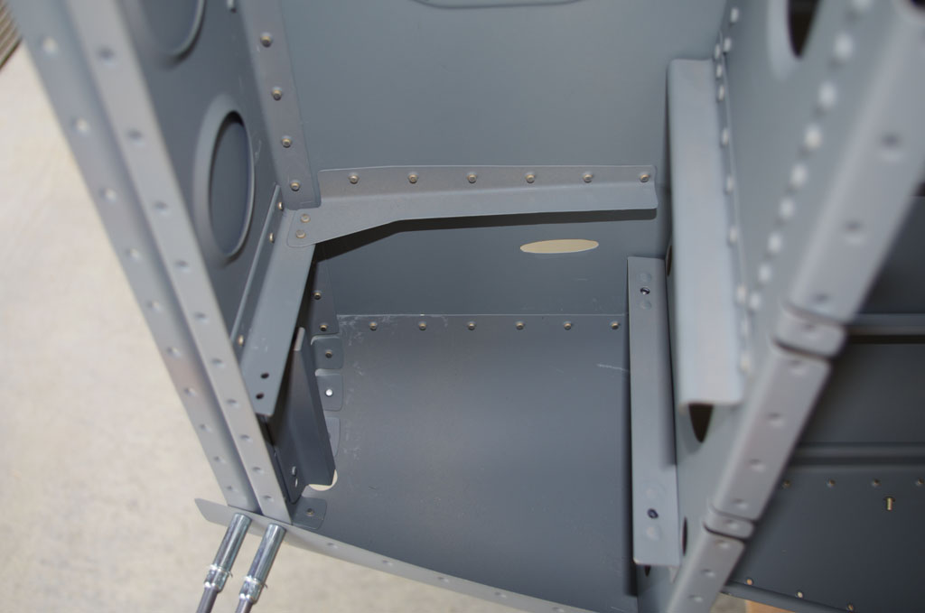
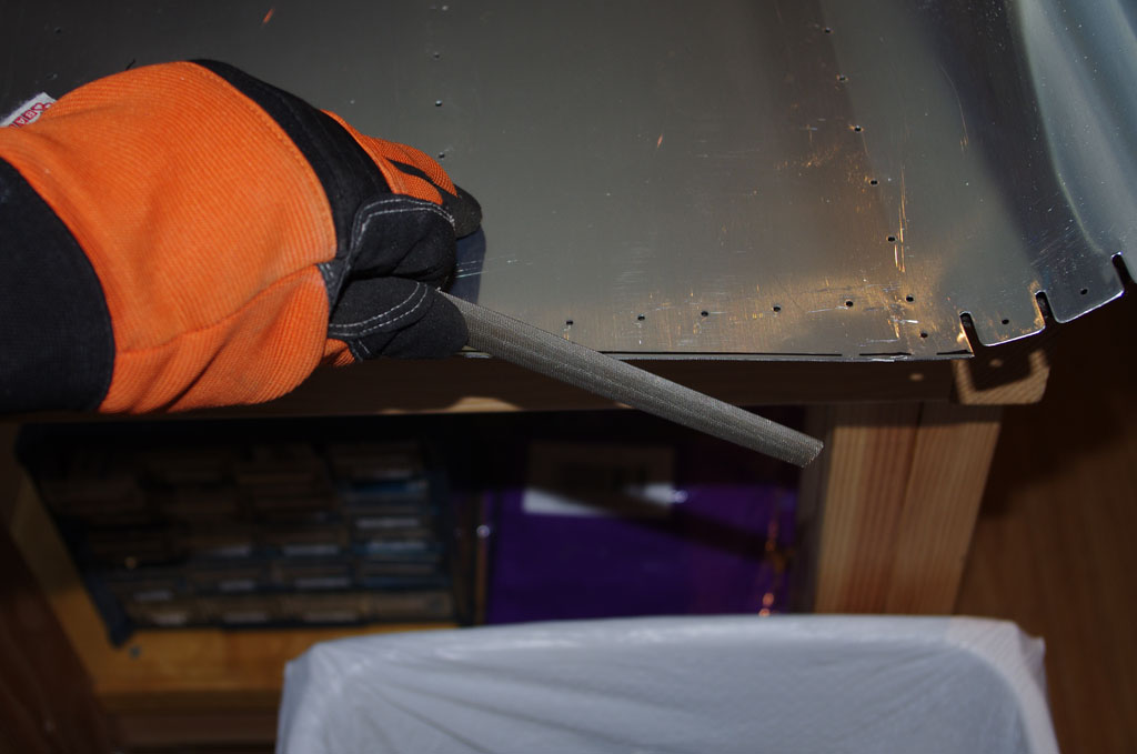
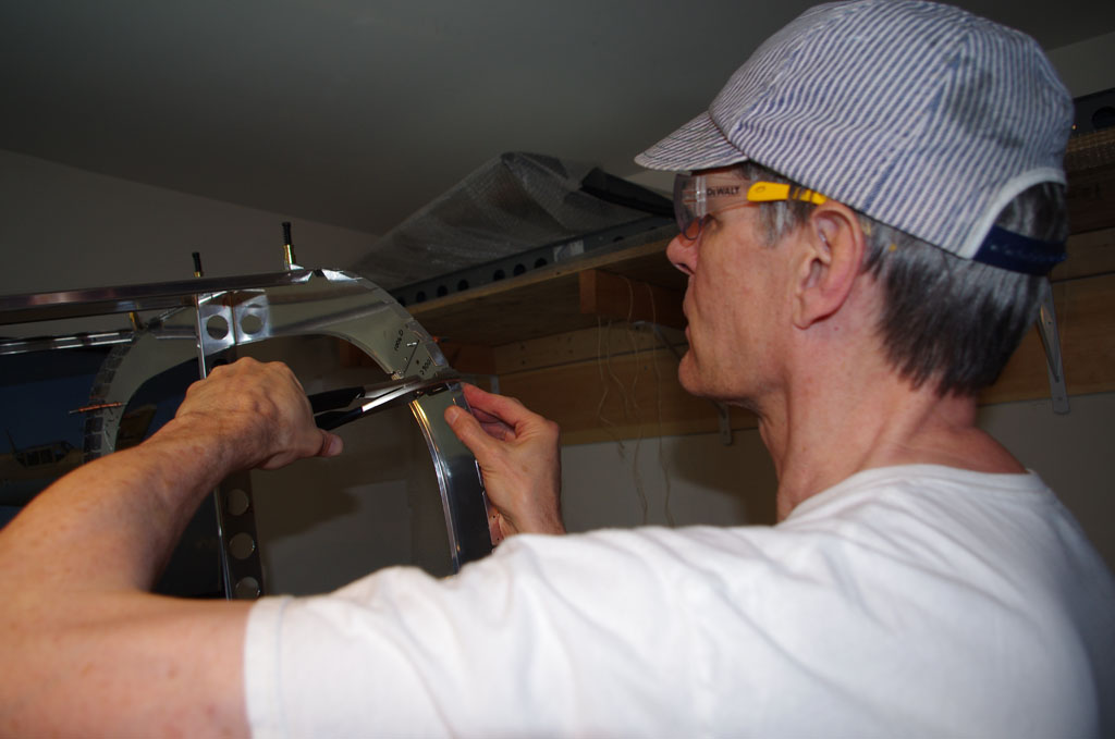
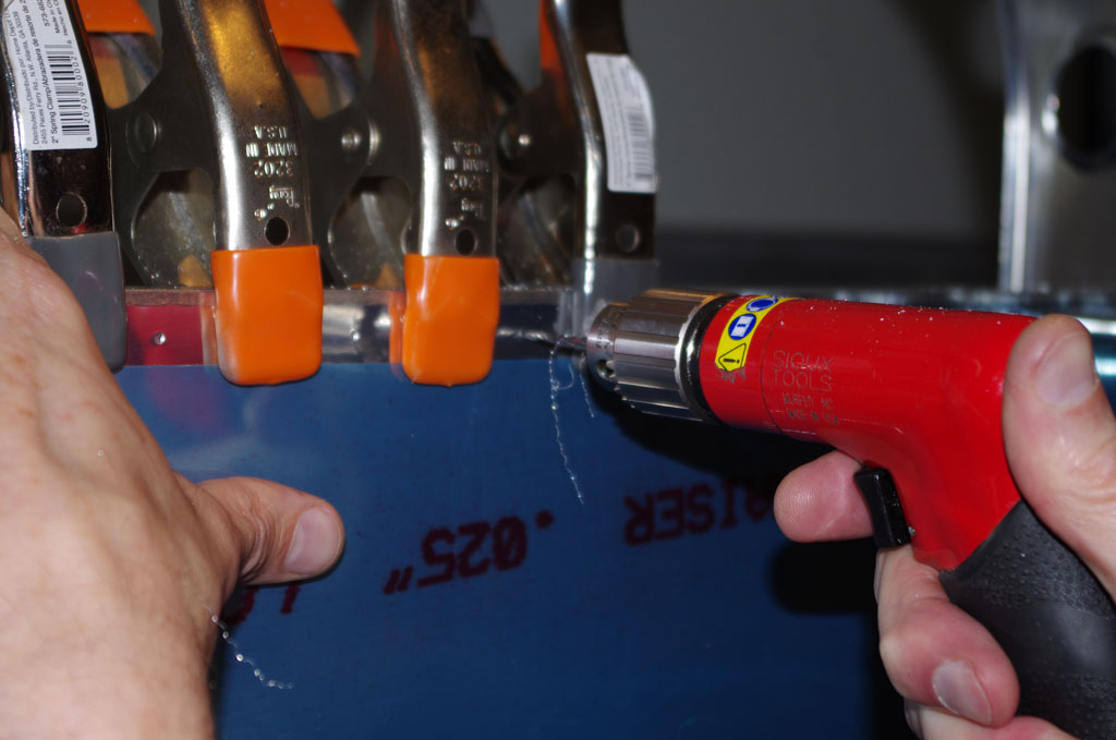
 The mid-skin is squeezed onto the longeron. Once completed the overall strength the unit is good. We did not get to the baggage door frames yet, as a question about the lower door shim placement needs to be resolved first. The plans are not very clear on this topic.
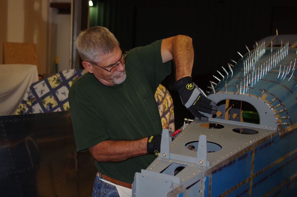
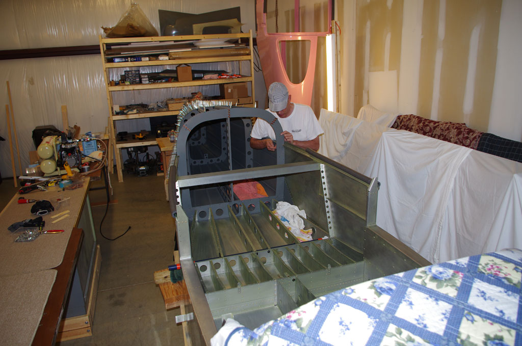
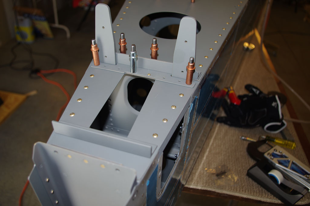
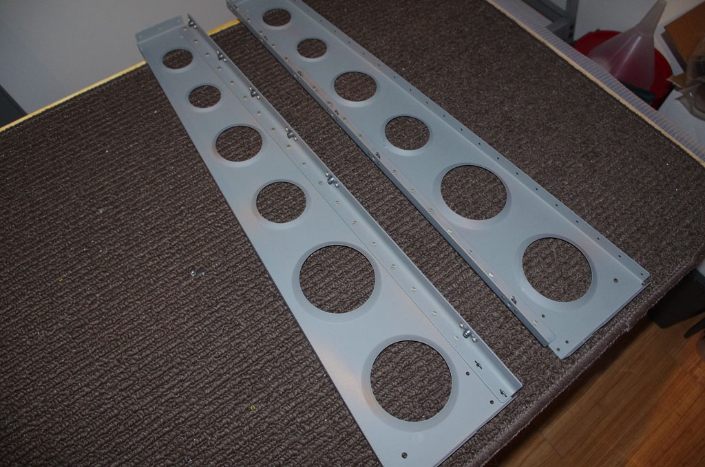
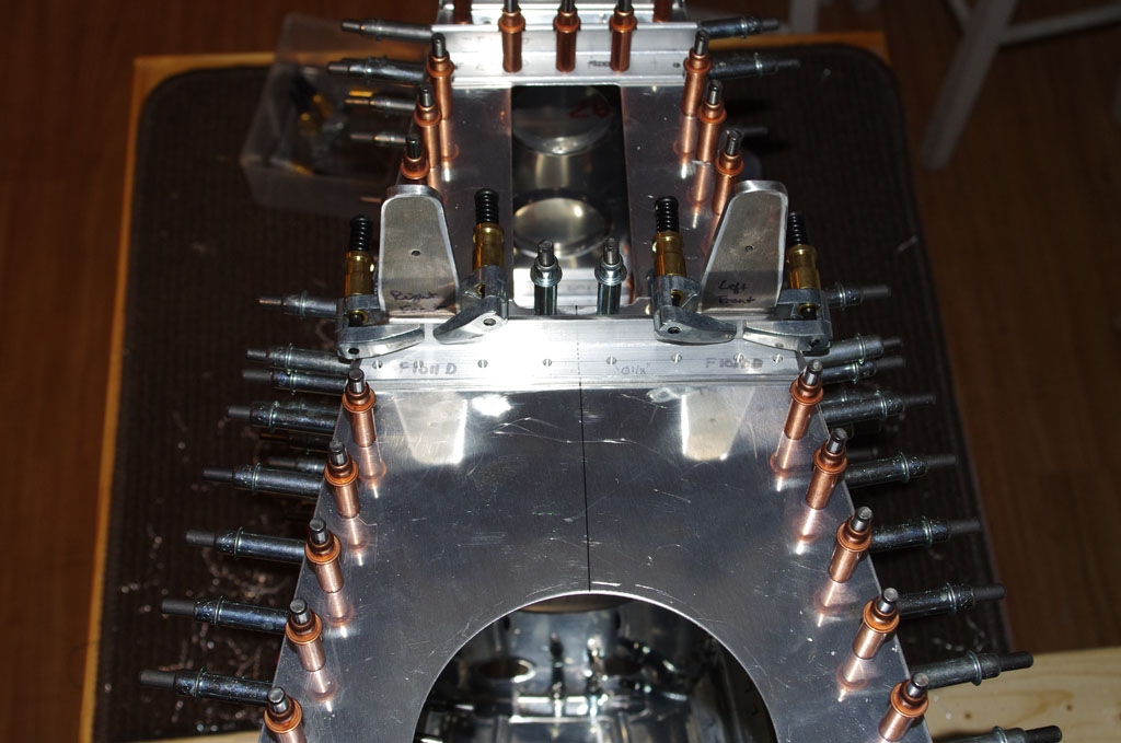
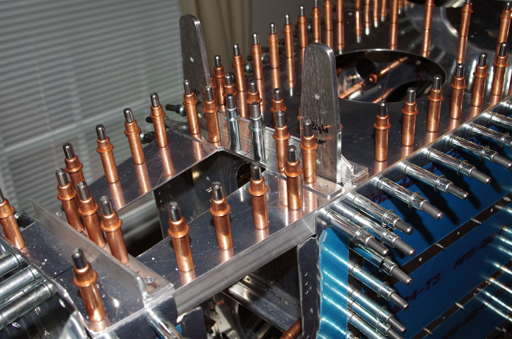
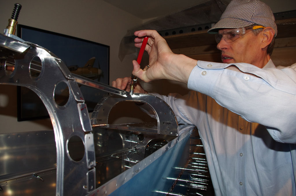
 Final step in the attachment is fasten the 8 baggage ribs to the baggage bulkhead. I used the 5″ yoke and pneumatic squeezer on the middle holes, but had to drive/buck the upper and lower holes on each rib due to access issues with flanges or tight fits. We had two drill-outs, but the final results are good.
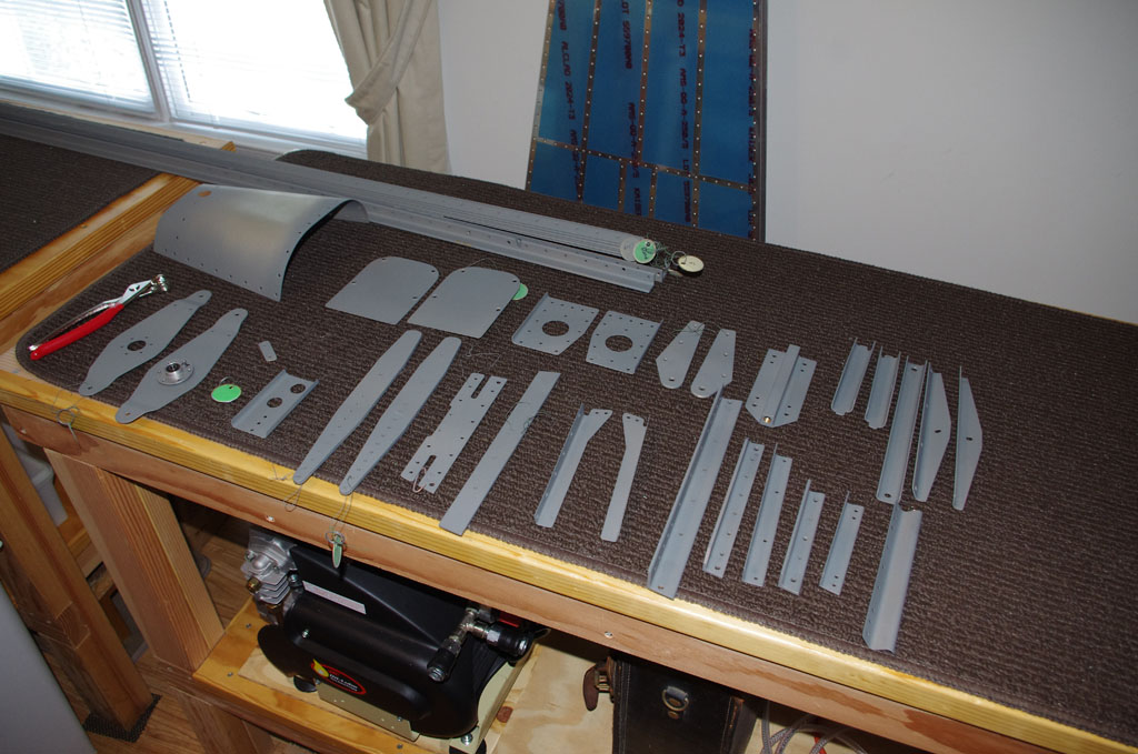
Next actions for me on the project will be fabricate mounting brackets in the tailcone section for air supply valves, NACA air vents, remote AHARS/magnatometers, and COM radios.