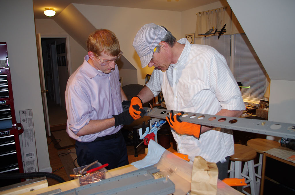
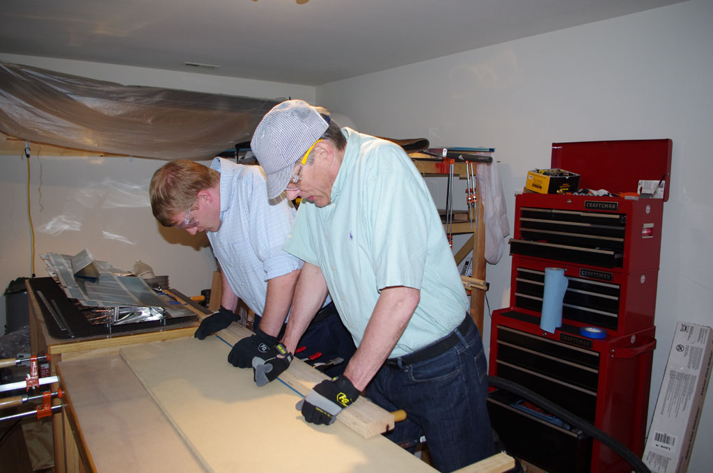
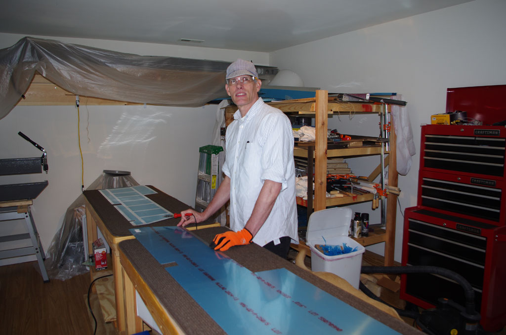
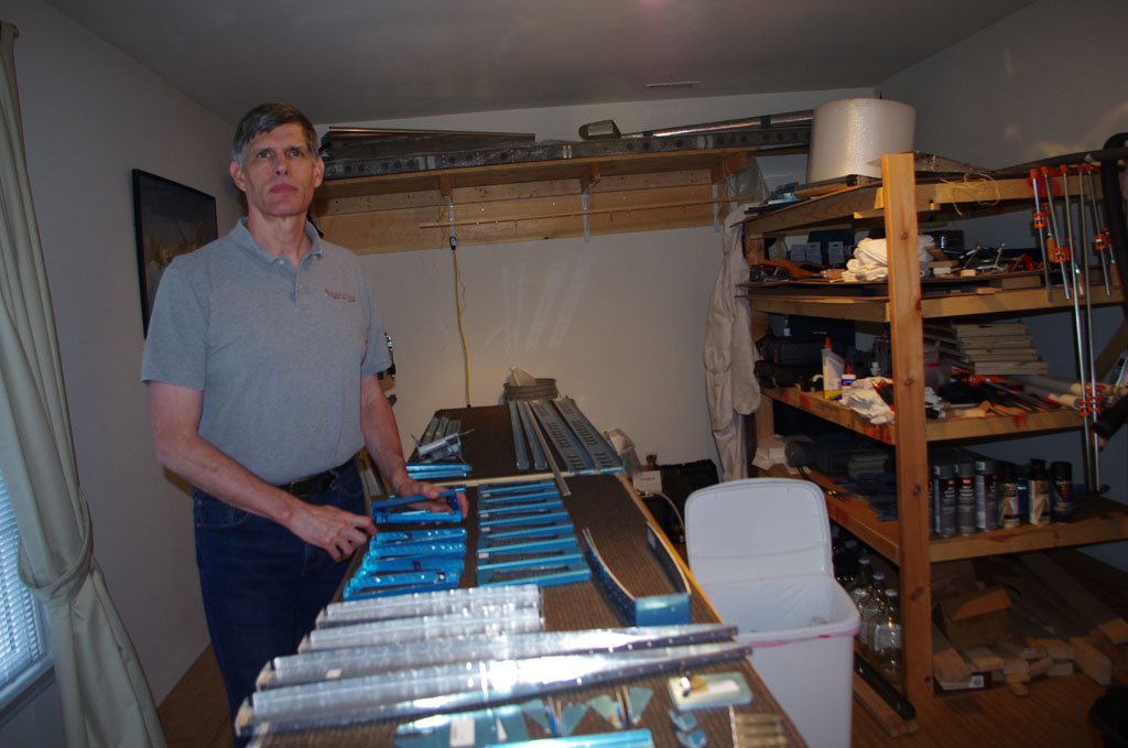
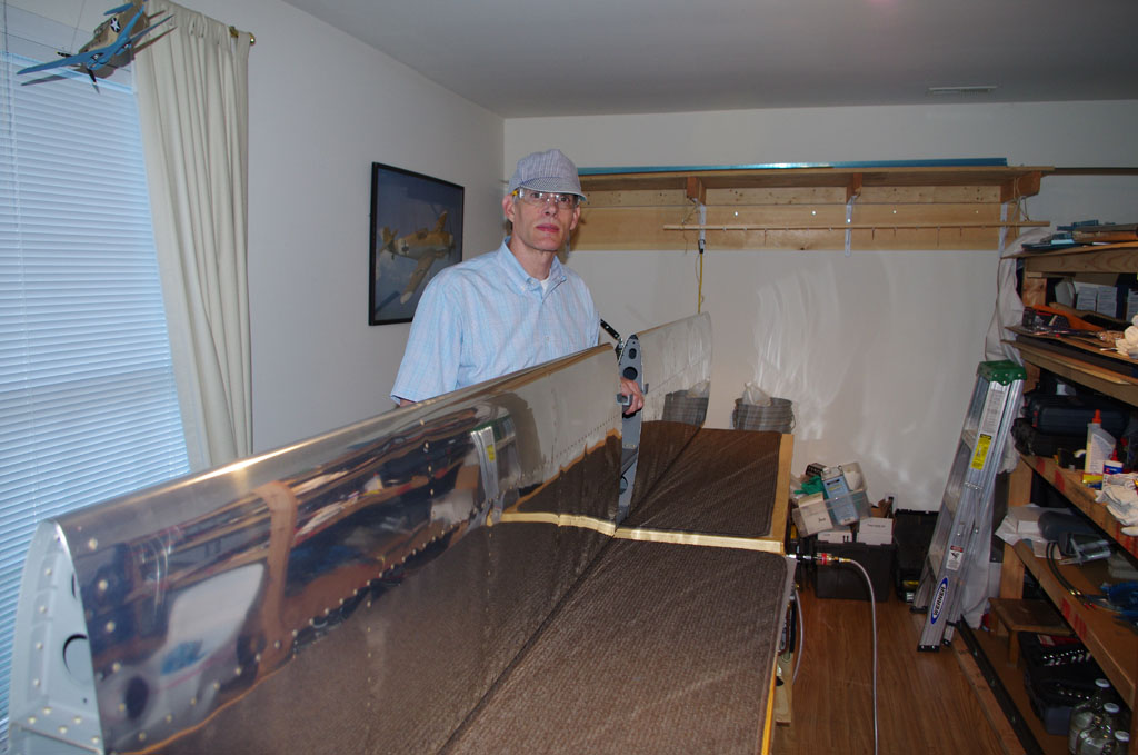
After many weeks of redoing the elevator trim tabs, adhesive bonding of the trailing edges and foam ribs was in order. Rich came over to lend an extra pair of hands during the process.

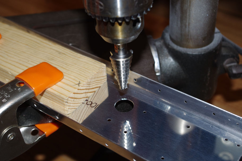
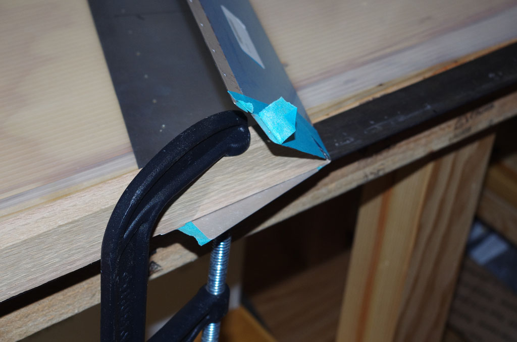 Bending the angled trim tabs was accomplished with a simple red oak board cut to a 45 degree angle, then clamped to the angle iron jig.
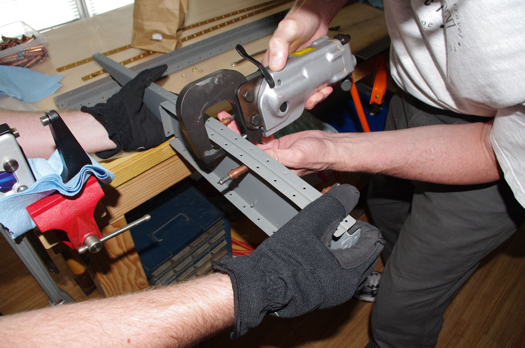
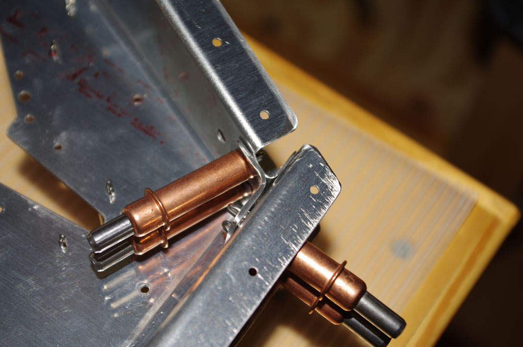
 Here the trim tab is sandwiched between two pieces of angle iron for bending the front part of the lower skin to 15 degrees.
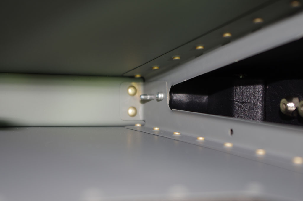
 A 12″ back rivet set was used with a standard backing plate to attach the lower portion of the trim tab spars.
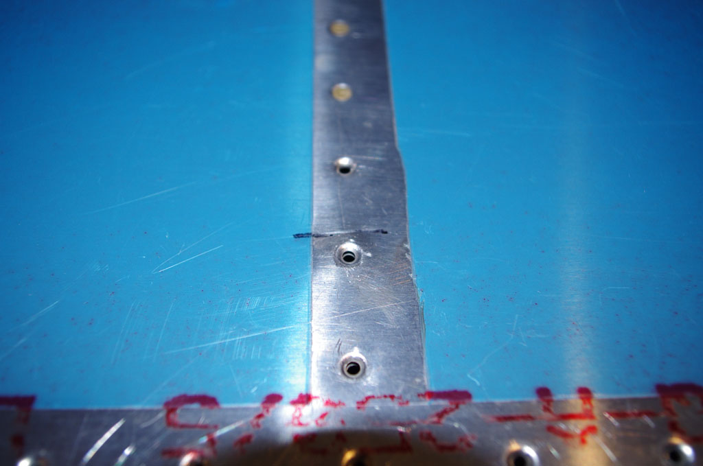
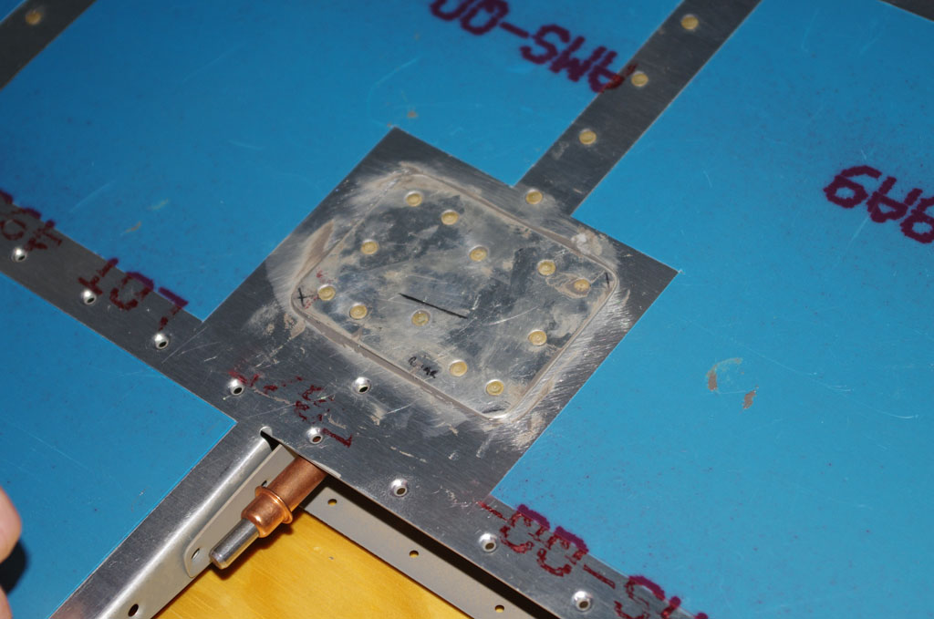
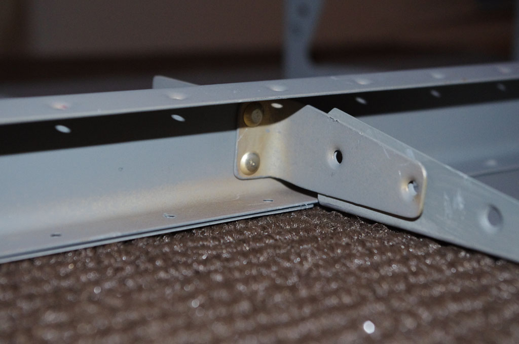
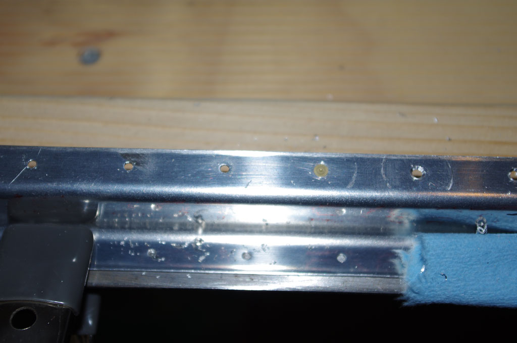
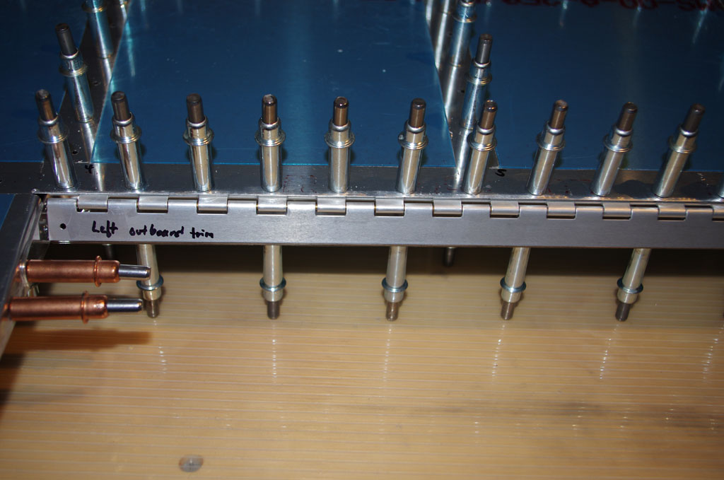
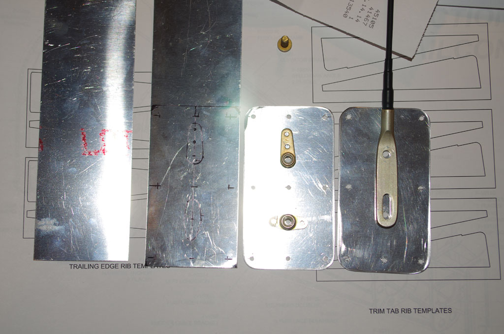
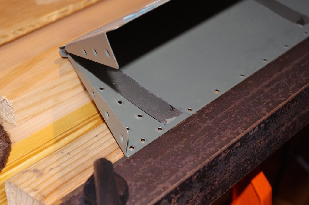
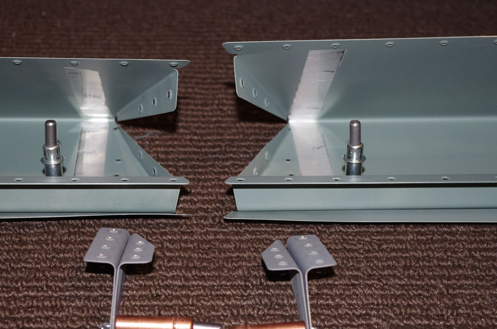
 Here is how the first set of trim tab horn rivets appear. More on the trim tabs later.
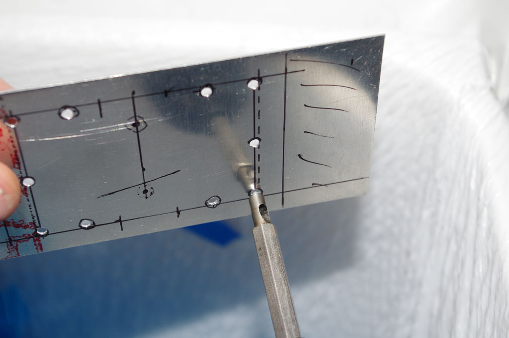
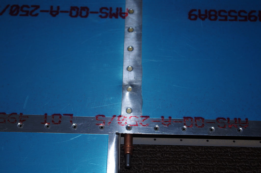
 Cherry Max 3213-4-3 structural rivets were used to replace the simple LP4-3 called out in the plans. Discussions with my technical counseler and an A+P mechanic indicated structural rivets can always be substituted for lower strength rivets of the same size. However, Cherry Max brand rivets are more expensive (about 63 cents apiece).
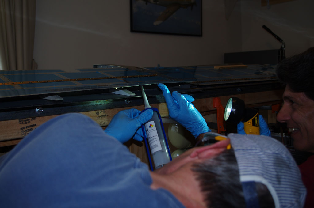
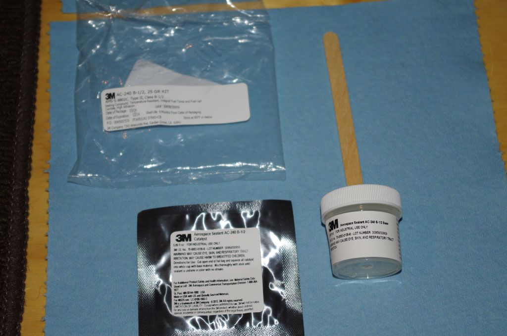
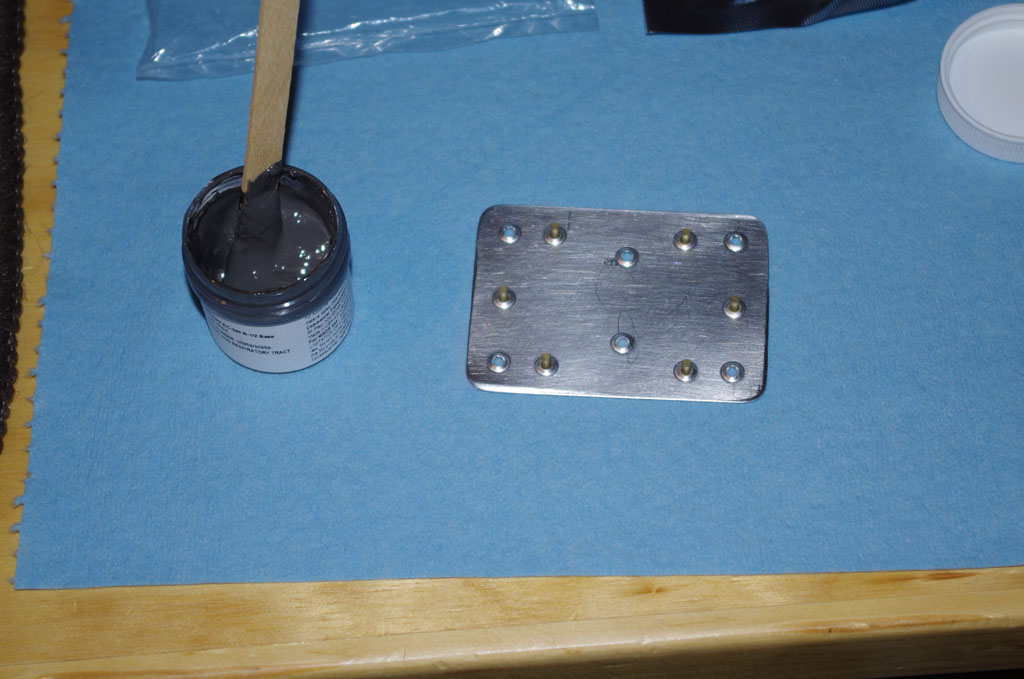
 On to the trailing edges – here the Van’s ProSeal equivalent is being applied initial application from with a caulking gun. I later used a wooden popsicle stick to smooth out to ensure complete coverage.
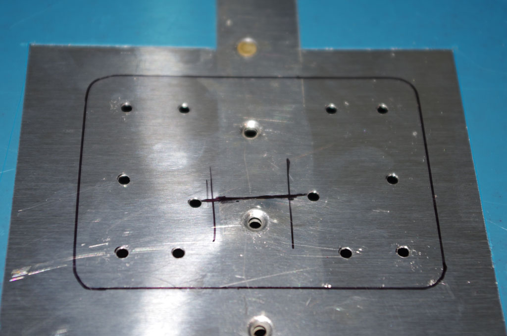
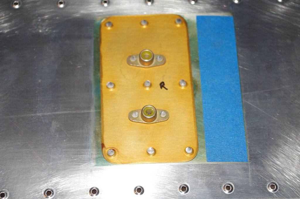
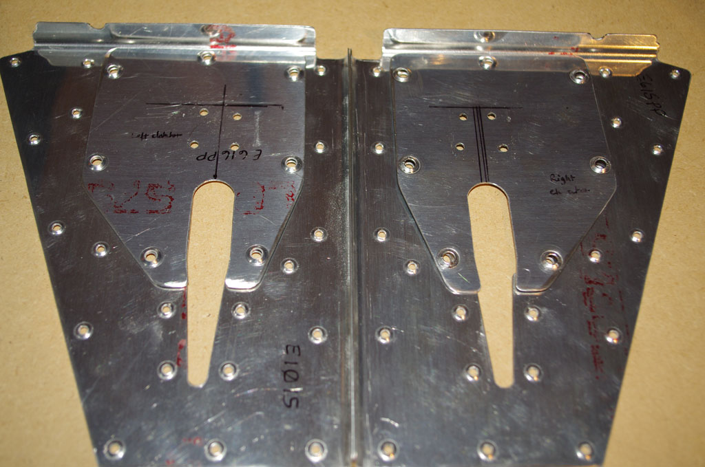
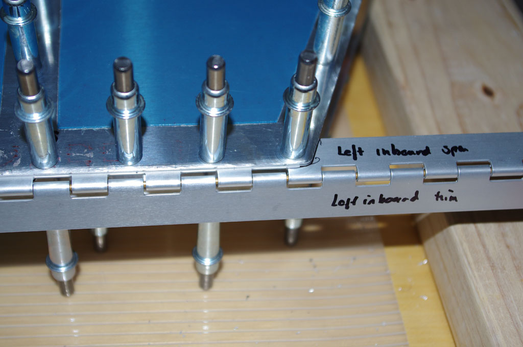
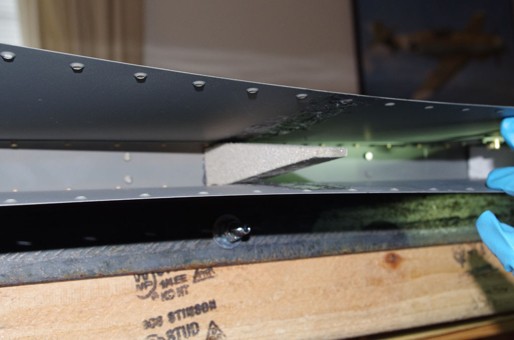 This shows the foam rib attached to the rear spar.
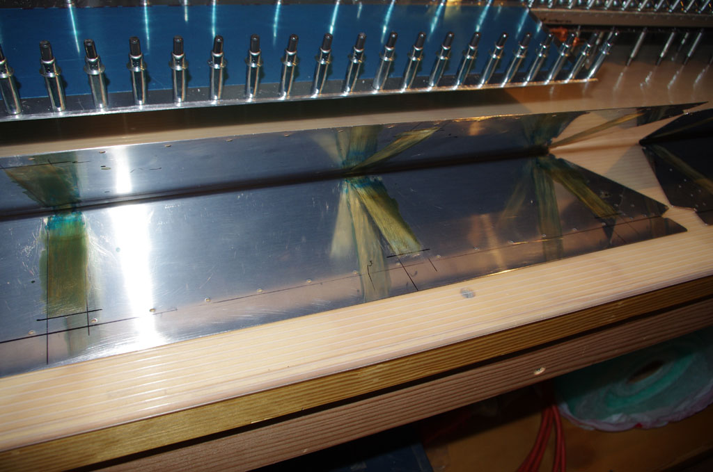
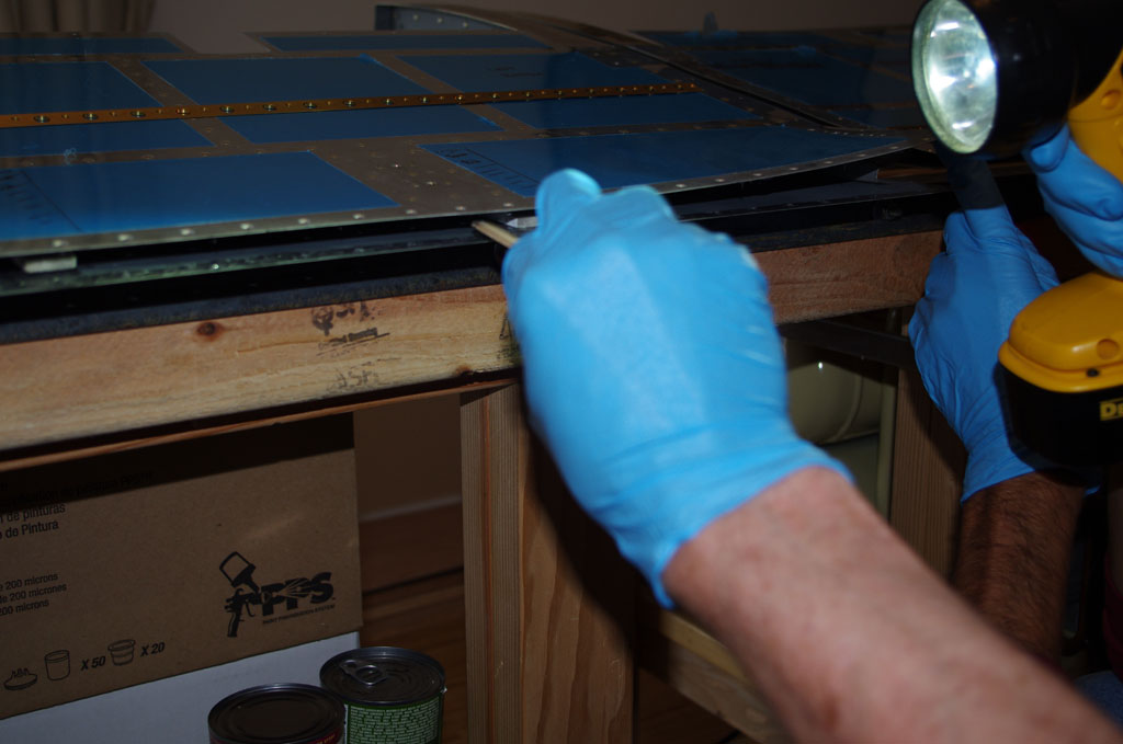 Smoothing out the bonding adhesive, getting ready to insert the trailing edge.
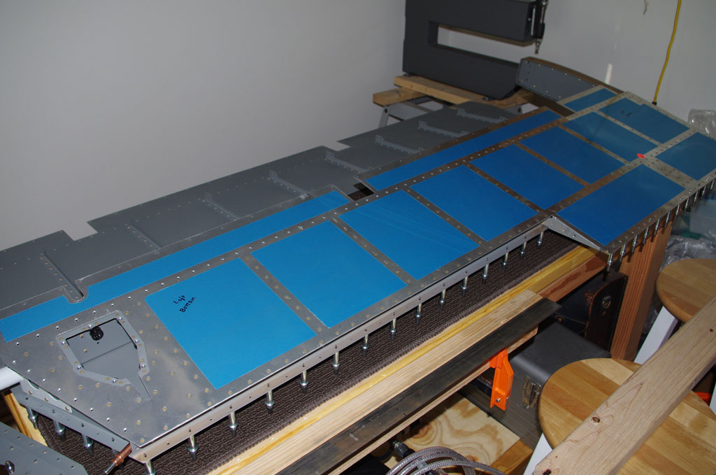
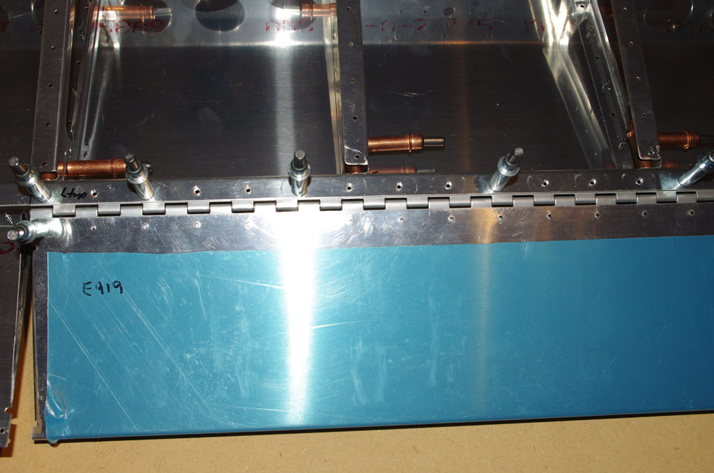
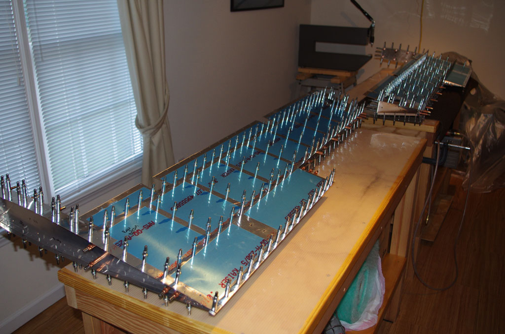
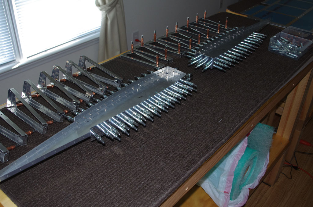
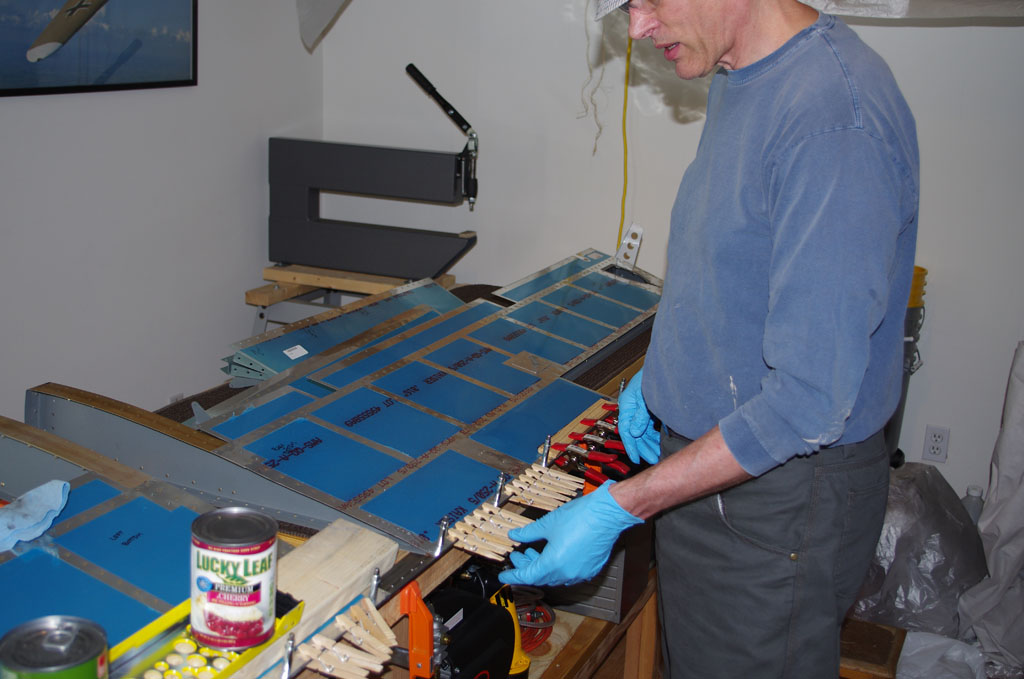 The trailing edge is clecoed to the angle iron jig about every 7th hole. In between are wooden clothes pins, then comes a 2×4 with weights to hold the skins against the freshly bonded foam ribs.
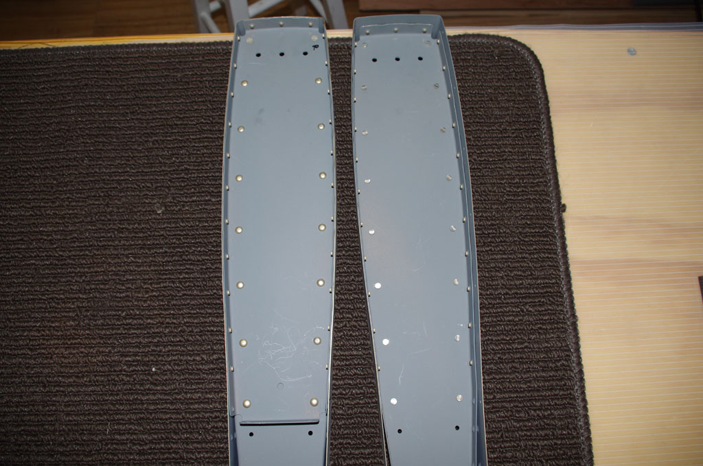
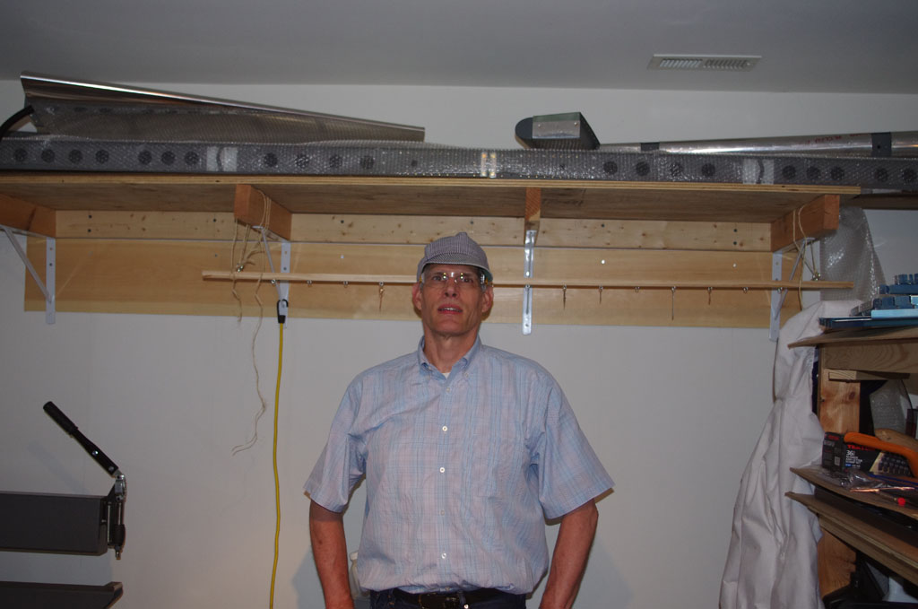
 The trim tabs were also bonded. This photo shows them in the wooden jigs holding the skins against their bonded foam ribs.
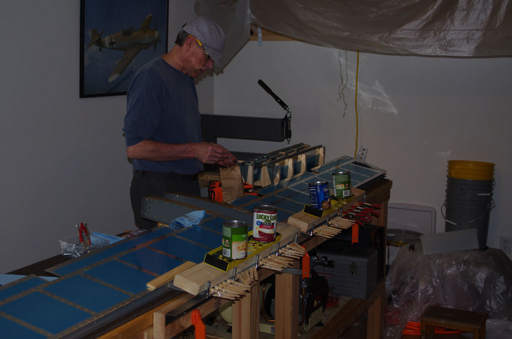 DONE. Now to let the adhesive cure for a few days before starting the final riveting steps.