Elevator Prime (Complete)

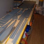
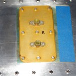
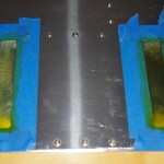
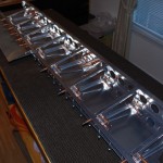
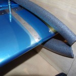
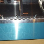
After work this week we finished off the Prekote and prime of elevator skins.  The most significant elements were masking off the scuffed area for foam ribs, and priming the riveted reinforcement plates for the static wicks.

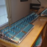
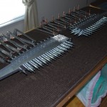
IMGP4444Ready for primer…


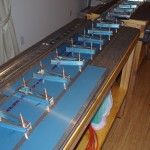
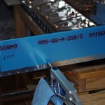
IMGP4446Done.  Next step is rivet assembly.


IMGP4447All the elevator parts primed and staged for assembly.  Rita and I are taking vacation in the NC mountains this coming week, so maybe a few rivets will get set over the weekend when we get back.


Elevator Prep (Alodine/Prime)

I took a half-day from work on Friday, then spent about 15 hours over the weekend with the routine for wash, scuff, brighten, rinse, alodine, and priming all parts except the skins.  The process is the same as described in previous posts.  Here are just some pictures of recent events.

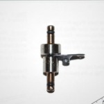
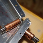
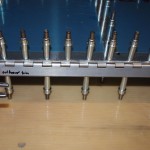
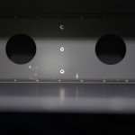
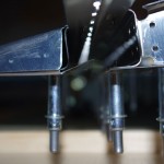
IMGP4435IMGP4424This photo shows the reduced cross-section on the special female 3/32″ die purchased from Cleaveland Tools.  Here the clearance from the screw recess is visible.  A picture of the regular die size is included for comparison. (see previous post on details)


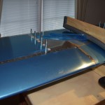
IMGP4437Alodine applied to the skins where foam ribs will be glued with ProSeal.  This process is the same used for the trim tabs.


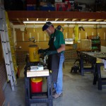
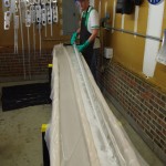
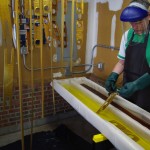
IMGP4439The garage is turned into a chemistry lab for the weekend…


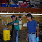
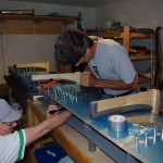
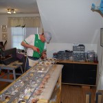
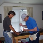
IMGP4442Happiness is when friends and family participate in your favorites hobbies.  Rich and Eric both helped greatly on a long, hot weekend of metal prep and priming.

Elevator Preparation (3)

This Labor Day weekend, Eric and I spent about 16 hours working on spars and skins. This took most of the time, but a few other activities showed progress as well.
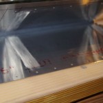
IMGP4398Scuffing the insides of the trim tab skins is necessary for a good bond with ProSeal at final assembly.
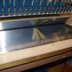


IMGP4399Plans call for bare metal, but I feel a good alodine coat will help prevent any unwanted corrosion under the foam blocks. My approach was alodine the bonding areas, mask off these areas, and prime the rest. The primer should be sprayed on before the skins are bent to the 10degree final angle needed for attaching to the spar. (The bluish tint on part of the alodine is from the Sharpie marking lines.)
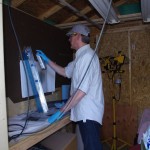


IMGP4408Here a SEM product (self-etching primer) is applied to the insides of the trim tab skins. Note the skins are still fairly far apart at this point.
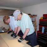


IMGP4413After priming is when the final bending occurs.  Eric helps me apply hand pressure with a 2×4 on the trailing edge.  We had to do this 10-12 times as the skins wanted to rebound back to their original shape.  I had been advised by my technical counsellor not to be to aggressive with an acute bend – else the edges would crack.  Gentle, repeated, and steady pressure did the trick.
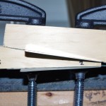


IMGP4419Bending the end tabs is also an adventure.  In retrospect, I would cut two oak boards and a 10degree angle for the bends. In addition a 1/32″ round could be applied properly to the oak wedges. This would dispense with the two sided tape, forward-backward slipping, and sharper than desired tab bend radius which occurred with these blocks.


IMGP4414After the bends, we fit and drilled the hinges to the trim tabs.


IMGP4428Countersinks are performed against the upper trim tab spar to accommodate a flush finish with the skin.


IMGP4433Here I use the Main Squeeze to dimple the trim tab skin.


IMGP4416Even using hand methods the results on the trim tab ends are not bad.
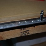


IMGP4422Here the angle iron jig is being used to hold the elevator trailing edges for countersinking.  I used this technique before on the rudder.
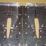


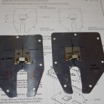
IMGP4423One of the trim cable anchor brackets turned out fine after dimpling.  The first reinforcement plate (right) was seriously misshaped by not aligning the DRDT machine correctly.  I have ordered a replacement part from Van’s, as all the pressure on the elevator cables is on these two pieces.  Live and learn…
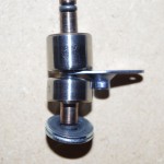


IMGP4424The trim cable anchor brackets also have K1100-06 nut plates to accept the #6 screws holding the reinforcement plates.  Unfortunately the nut plates themselves need to be dimpled for the flush rivets. The default die set is too wide, and deforms the screw recepticle.  Cleveland Tools does sell for $19 a special low profile female die for exactly this function.  My order should arrive this week.
Elevator Preparation (2)

This week’s work centered around match drilling all skins and spars.  A number of miscellaneous small parts and jigs were also completed.

IMGP4380The gusset pieces in the corners reinforce the elevator at the rear spar and root rib junction. After the skin were clecoed in place, this whole assembly was very rigid, amazing for being made from such thin parts.


IMGP4386Here everything is clecoed together, ready for the evenings of match drilling of the skins to spars and ribs.  Eric helped on all these.


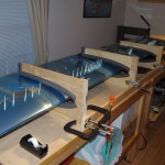
IMGP4392The trim tab has foam blocks attached with ProSeal compound instead of ribs/rivets like the rest of the elevator. The wooden blocks will be used to hold the skins in place against the foam ribs while the adhesive drys.


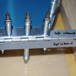
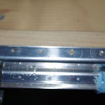
IMGP4395IMGP4396Here the hinge for the trim tabs are fitted and drilled to the upper rear spar flange. Eventually the excess length will be removed, but the extra pin length will be secured with safety wire.

Elevator Preparation (1)

Interim activities include preparing the trim tab, spars, and skins by fitting, match drilling, deburring and smoothing. My original post was lost with some server hosting issues, so I will recreate as time allows.  In the meantime here are some quick pictures (comments to be added later)

IMGP4349One of the big challenges with this build is the logistics necessary due to the space contraints of using the bonus room as a shop.  Some folks have the luxury of  setting up their dunk tank and leaving in place until the next use.  I have to setup and breakdown after every operation.  As a result, batching as many parts together as possible is highly desirable, even if this requires jumping through steps not in sequence as outlined in the plans.


IMGP4351

The elevator tip ribs were the first to be fitted together. These were then match drill as indicated in the plans.


IMGP4356

There are 16 pairs of internal ribs between the front and rear elevator spars.  Fitting and drilling these was the next order of business.


IMGP4357

Keeping track of each rib location will be tricky, as there are so many which look exactly alike.  A recent “Mistake Proofing” course from ASQ recommends parts configured for assembly in only one way – certainly not true here. I eventually used floral wire and tags to identify positions 1-8 on the left side, A-H on the right side.  This scheme was retained through priming, where I finally labeled each part with a Sharpie.


IMGP4360

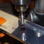
A 5/8″ Unibit in the drill press created the proper diameter for the elevator cable grommets.  Once the holes are drilled in the appropriate locations, the previously identical spars now only work one way.  This fits the “mistake proofing” model and allowed subsequent operations without special markings or handling procedures.


IMGP4364

Left side spars and ribs are clecoed to the bottom skins ready for match drilling.


IMGP4366

The Cable Anchor Attachment Brackets are measured for alignment prior to drilling for rivet holes. The nuts/plates welded together appear to be steel.  These will be primed with SEM self-etching primer before assembly with the aluminum alloy backing plates.


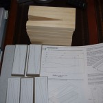
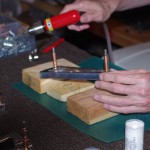
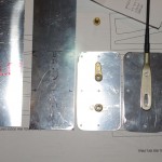
IMGP4371Here are the static wick reinforcement plates from raw material through to the final product.

Elevator Staging

As usual for a new section, I laid out the parts for an initial photograph.  The next few weeks will be spent on my least favorite part of the build – filing and deburring of the edges parts.  I don’t really mind using the Scotch-brite wheel, as a level of recognizing progress and a sense of instant gratification are present.  Okay, just heads down and get through this part…

IMGP4346

HS Completion

This week I finished squeezing all the spar rivets, which concluded the standard build portion of the horizontal stabilizer.  My technical counselor suggest 5 drill-outs on the inner spar sections, so these have also been completed.

IMGP4331Squeezing the spar rivets is a one-man job, so these were completed alone.


IMGP4335Eric did stop by for bucking the inner spar rivets and setting the final 25 inch/pound torque on the center hinge bracket bolts.


IMGP4339The final product is good, but not as clean as I would have liked. A few minor optical dents and dings, but should be safe otherwise.


IMGP4342All the finished parts so far (rudder, VS, HS) are stored on the overhead shelf to avoid “shop rash” from being bumped during the processing of other parts.  I used 18″ bubble wrap between the parts, and eventually covered all with thin plastic to keep out dust and dirt.  The nice part is being in the bonus room, temperature controls and humidity are not a problem.


IMGP4345Done with Section 8 of the manual.

HS Riveting

This week was all about riveting the horizontal stabilizer parts together.  The whole job is not yet complete, but good progress was made on bucking the nose, spars and some inboard ribs.  I had help from both Eric and Rich during the period.

IMGP4299Oops. Notice the small, but still visible blemish near the most forward rivet.  This came from the tungsten bucking bar pounding the reverse side of what we were processing.  The bar as I held it was wide enough to span from one skin side to another. Drats.  For later rivets I rearranged holding the bar parallel to the rib, not perpendicular to it as in this case.  Hopefully this can be smoothed away with filler before painting.  The only saving grace is this appears on the underside of the horizontal stabilizer.  People will have to bend over and look from beneath to see it.


IMGP4300During the week and after doing the nose ribs, I prepped for riveting along the spars.  AN426AD3-4 rivets are used for the outer section, AN426AD3-4.5 for the inner parts where the spar caps are located.


IMGP4310Eric comes over after work most nights for dinner.  On this occasion I pressed him into service for a few hours doing the outer skin-to-forward spar rivets.


IMGP4314Here are the prep stages for the inner spar riveting.


IMGP4317Rich came over on Saturday to help me complete the upper skin riveting in its entirety. The small cells between the stringers, inboard ribs and spar are quite tight for my big hands.  It takes lots of repositioning of the bucking bar to see well into those cavities.


IMGP4319Here’s what it looks like on the outside as of Sunday morning.  All the upper skin rivets are set (actually the bottom on this photo), the lower skins have been riveted to the forward spar.   The inner rivets and placing the rear spar up for next week.
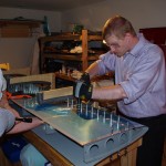


IMGP4324Upon inspection I found a number of scratch marks where the bucking bar had rubbed against the spar during rivet setting. This happened despite putting duck tape on the forward spar and the bucking bar for protection. My plan is to get a small Preval brand sprayer to prime over this spots before closing off with the rear spar.
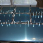


IMGP4326Another trick employed was fitting a felt chair leg cushion to the end of the bucking bar. When used in conjunction with duck tape against the spar, this seemed to eliminate any scratching.  Another prime example of live, innovate and learn.


HS Prep and Assembly

Although I have not posted in a few weeks, much activity has been occurring on the horizontal stabilizer.  Three long weekends in a row have gone into drilling, scuffing, washing, brightening, alodine, priming and assembly.

IMGP4242May 24 – final stages of jigging and match drilling complete.


IMGP4247May 25 – Rita, the not-yet Riveter. Here she is helping me dimple the HS skins with the DRDT-2 machine.


IMGP4255May 26 – mixing the DP401LF catalyst with the DP40LF priming for the HS skins.  First the skins were washed with Pre-kote, then dried in the shed.


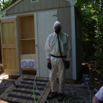
IMGP4258May 26 – suited and ready for skin priming.  Not much can be seen inside the shed once priming starts.


IMGP4271May 31 – dunk tank extended to 12′ to hold the HS spars.


IMGP4272May 31 – brightening underway. This was the first time I used the garage for corrosion treatments.


IMGP4280May 31 – another view of the extended dunk tank.  One of the spars is bubbling in the phosphoric acid brightener on the right, a rinse tank is on the left.


IMGP4287May 31 – the alodine is on the right, rinse on the left.


IMGP4289June 7 – all parts are primed and ready for riveting.


IMGP4290June 7 – Rich came over to help rivet on hinges, attachment brackets, spar doublers, caps and stringers. We squeezed as many rivets as possible, only had to buck 6 rivets on the custom made attachment brackets.  Turns out the bracket, spar flange, and doubler combination is too thick for my Main Squeeze 3″ yoke (takes a 4-10


IMGP4292June 8 – the internal parts of the stingers and ribs must be riveted together before attaching the skins, because afterwards there is no access.

Tools

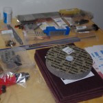
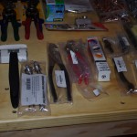
Many speciality tools are needed to fabricate a kit airplance.  I spent years researching the subject and still did not have enough information to get it right the first time.  However, my first bulk purchase went to Cleaveland Tools in Ames, IA for their RV10 starter package.

IMGP3271Here is the original packing list.  Eric and I did a full inventory on the first shipment, only found one issue needing correction.  Some tools were back-ordered, but otherwise responses from Annette from Cleaveland have always been immediate, friendly, and helpful.


IMGP3259IMGP3262This package was slightly under $3000, but I have subsequently gone over that number as the work has progressed. However, I can confirm what every builder already knows – you can never have too many tools!


IMGP3269IMGP3268IMGP3265