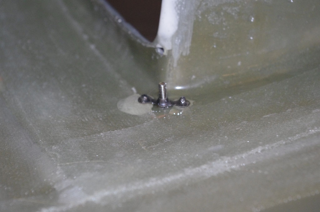
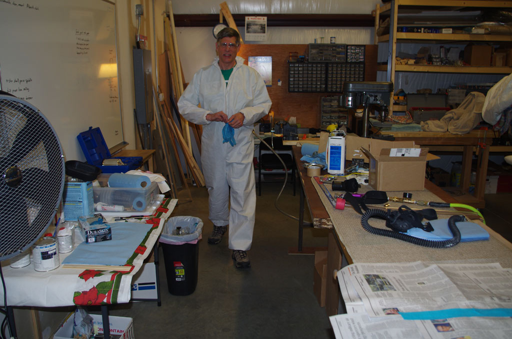
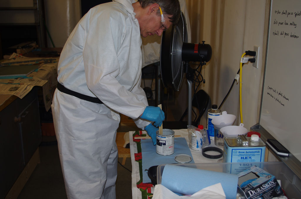
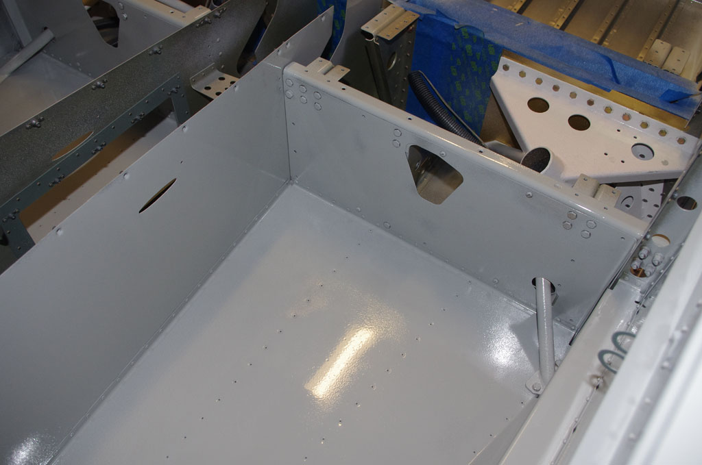
Painting the interior last week has unlocked a number of different activities which can now be undertaken. The Fourth of July 2016 weekend was used for installing things which have been prepped and staged for quite a while. The sequence of activities was based on time of day (heat in shop), and whether solo work was possible or another set of hands was needed.
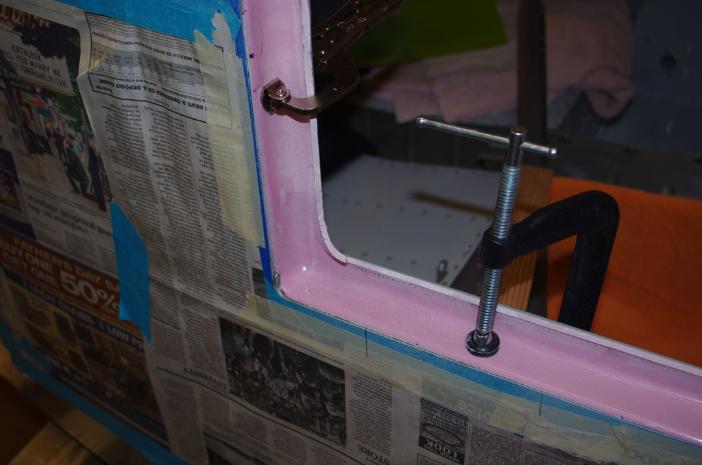
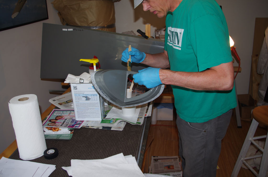
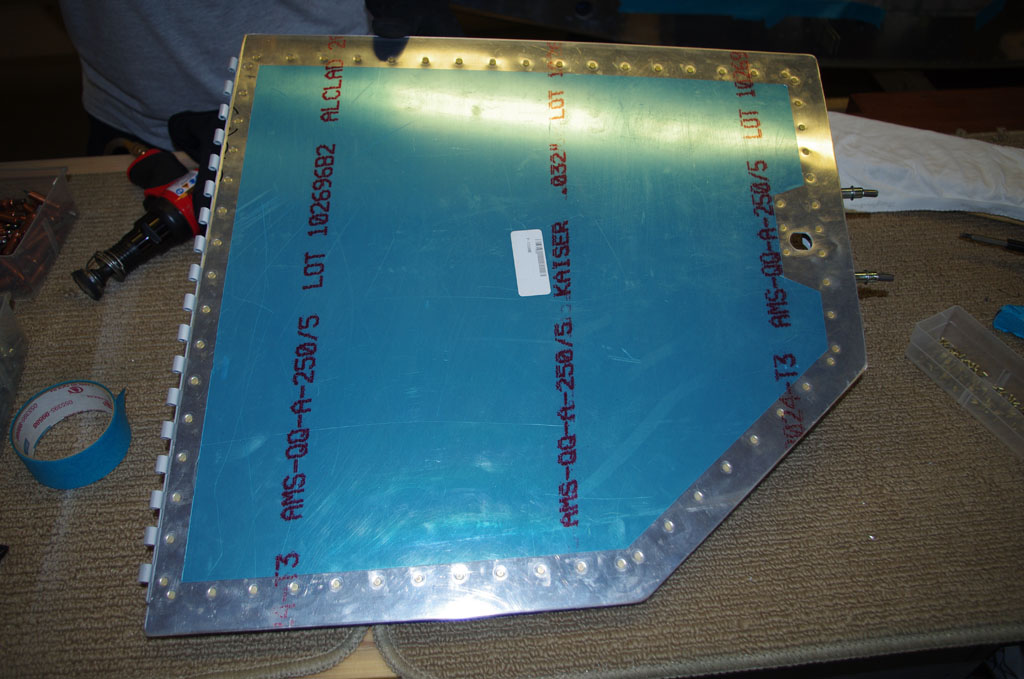
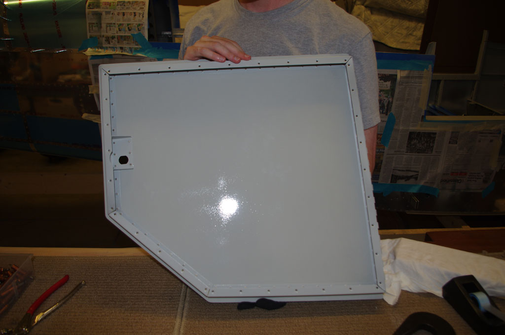
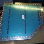 A few miscellaneous parts were also painted last week. Here the outer baggage door panel is riveted onto the frame. Eric helped by driving from the exterior side, while I bucked from the inside.
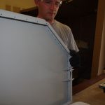
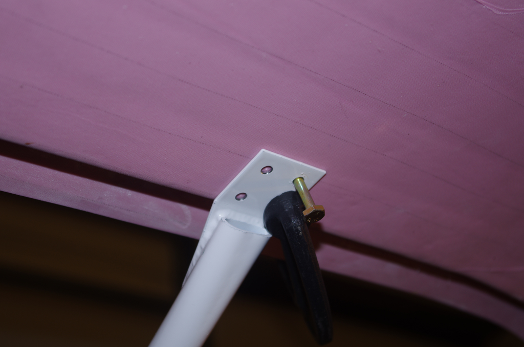
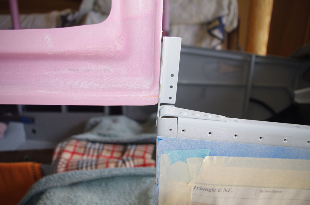
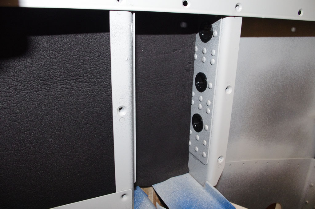
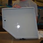 Here are two different perspectives of the baggage door from the inside. The next step is fit 1″ sound damping insulation, then pop rivet the inner panel to the frame. Last step will be install the door lock/latch, but this will be after the cabin door hardware is acquired.
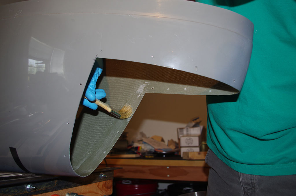
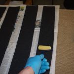 Saturday morning saw foam soundproofing material installed with contact cement. Rich had cut these several months ago on a previous visit. The directions say let sit for 15 minutes before bonding the two surfaces, but this caused instant adhesion between the parts and some mis-aligned panels until I figured it out. For this foam material/ cement combination the best approach is put a thin coat on the plane, followed quickly by the foam – then immediately fit together. This leaves the contact cement just a bit slippery and able to slide just a little, enough to help position the panels better.
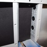
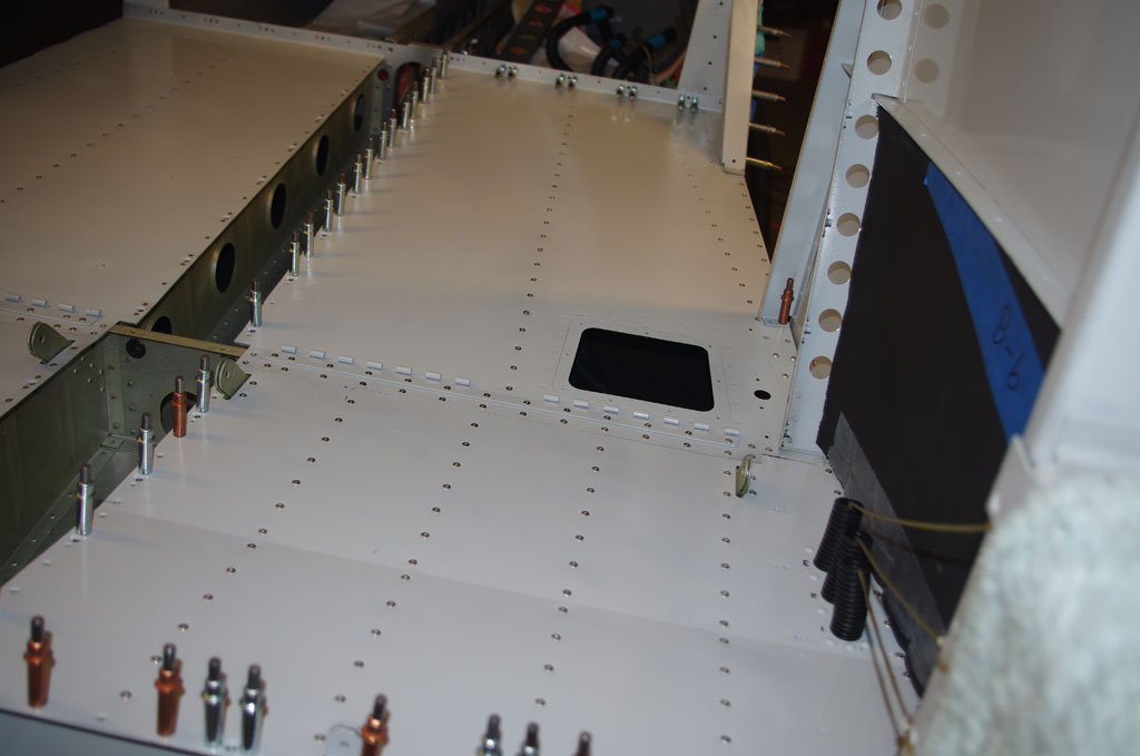
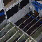 Here are views for the side panels and underneath the rear floor panel. All is not pretty, but not to worry. All the foam installed so far is covered by another interior panel and will not be visible. I hope the sound-dampening effect proves worth the effort involved.
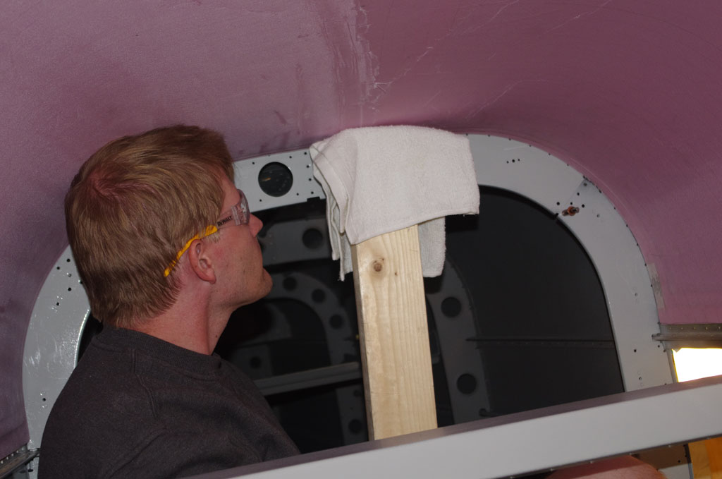
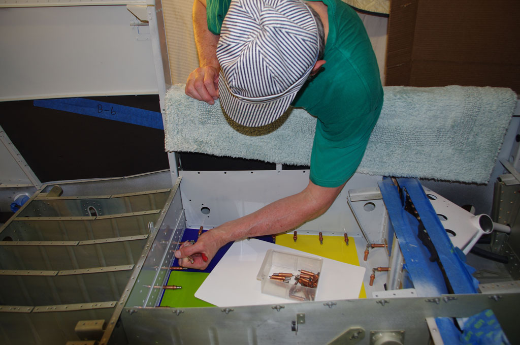
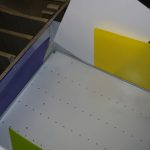 Okay, interior painted and foam applied. Now fit the rear seat panels and rivet in place. The photo shows thin plastic cutting boards ($8 for 5 sheets from Amazon) used to protect the side wells from being scratched by the panel on insert. This worked great and no damage was done.
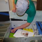
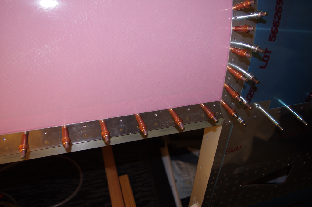
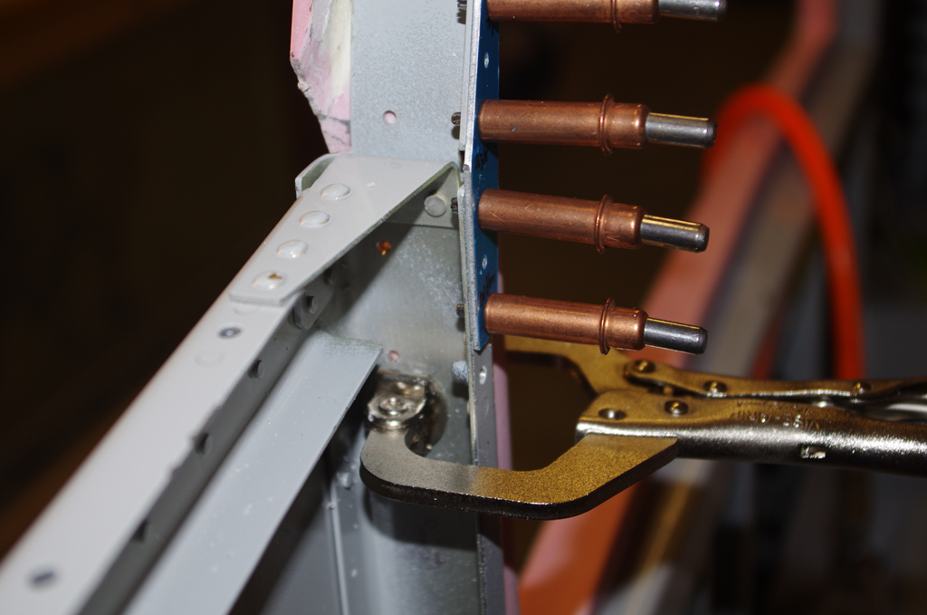
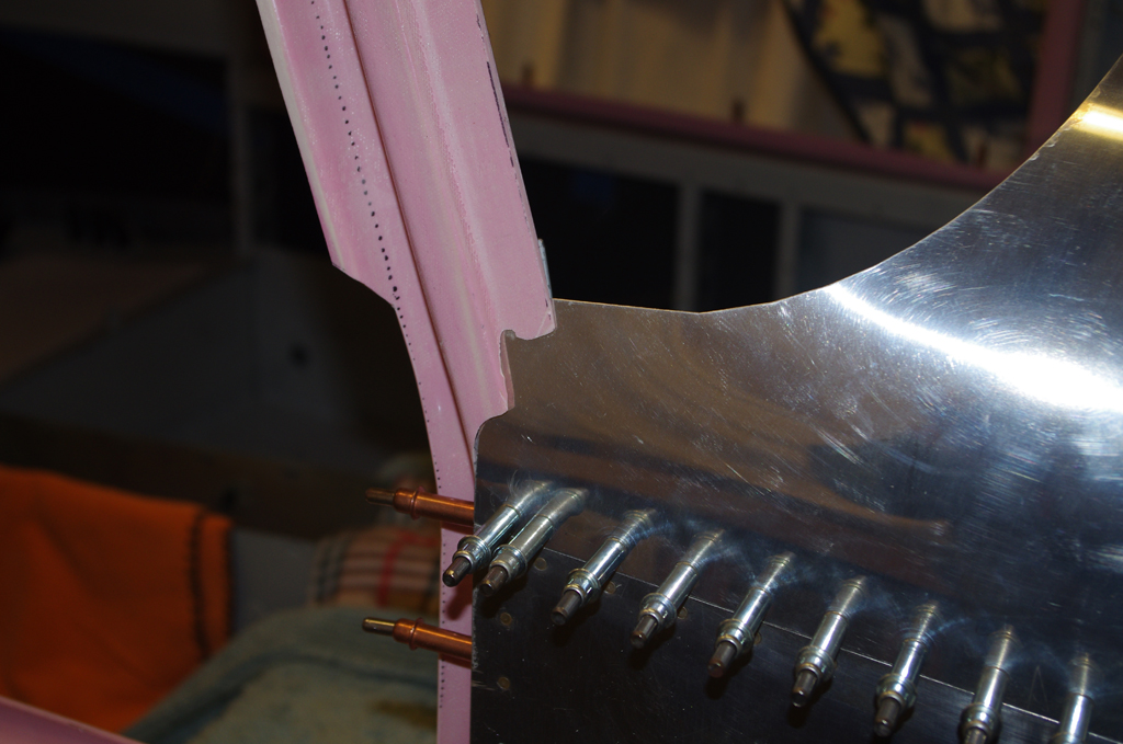
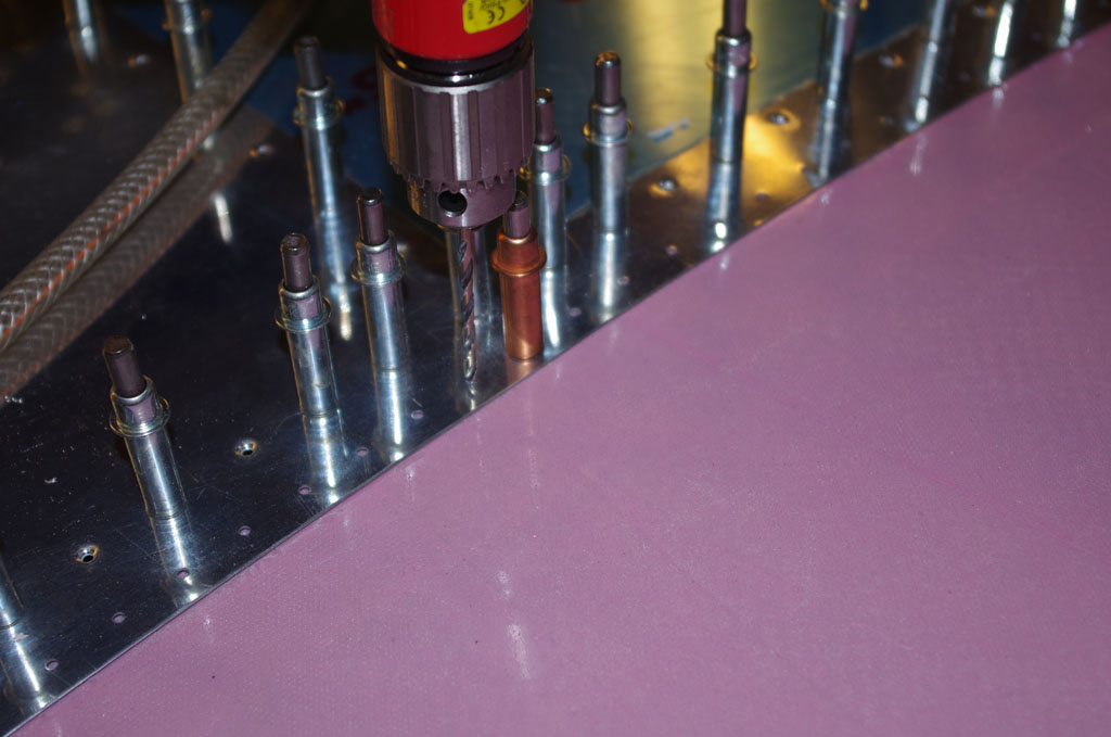
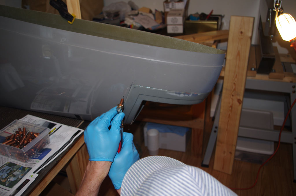
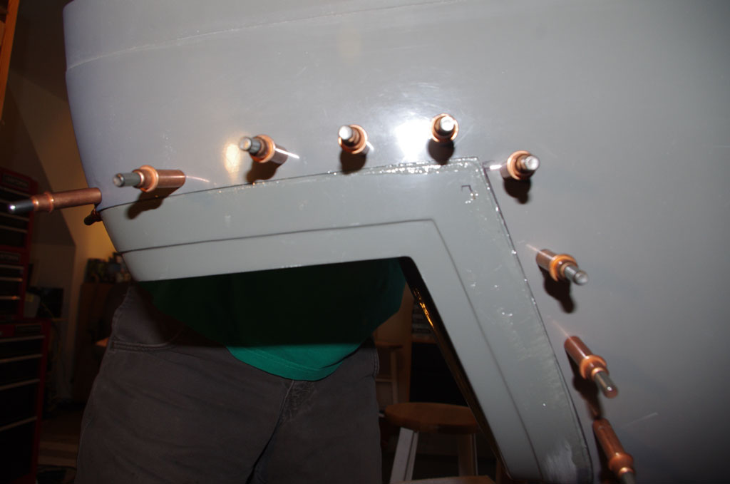
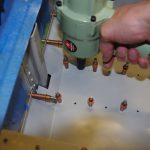 Floor panel is clecoed into place, then the floors pop riveted to the ribs underneath. I used a pneumatic riveter borrowed from Tal for the cheap ones with easy access. More expensive, but delightfully easy to use, CherryMAX CR3213-04-02 rivets were installed in the difficult corners with the offset head on the 704B riveter.
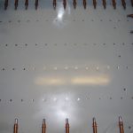
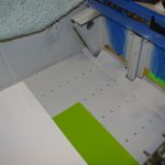 The left picture shows the completed floor/rib rivets, while the right picture shows the fully completed effort. The plastic cutting sheets were used to protect the floor as the side rivets were installed.
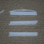
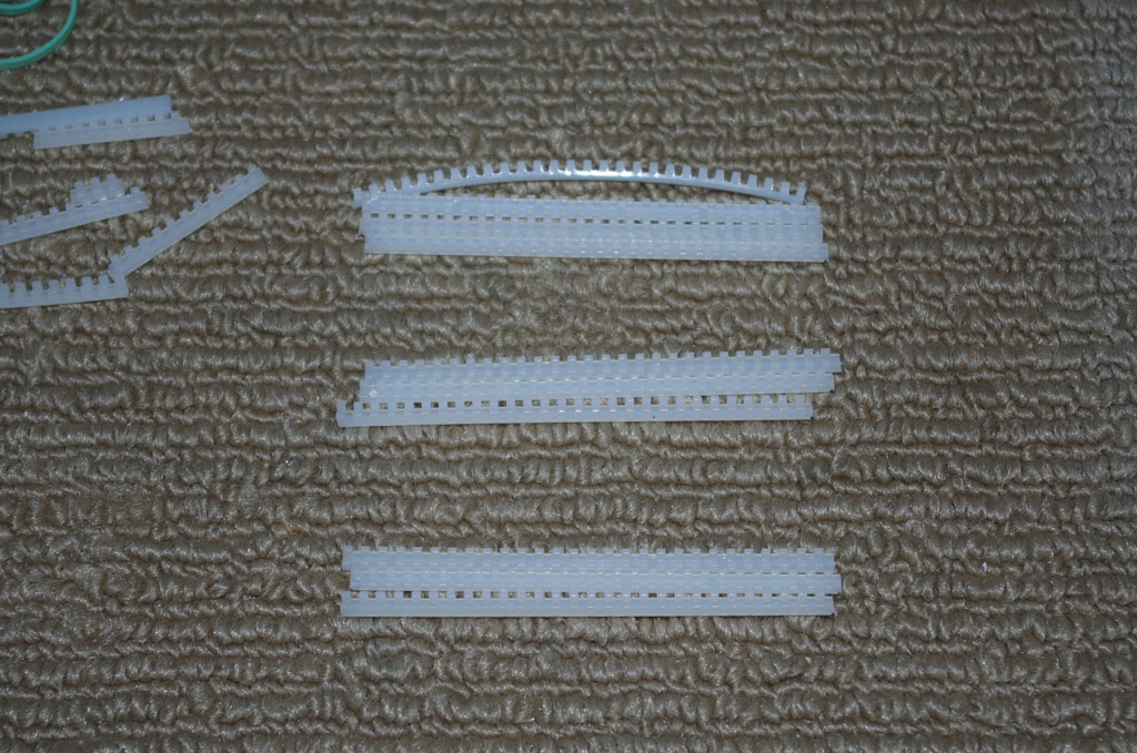
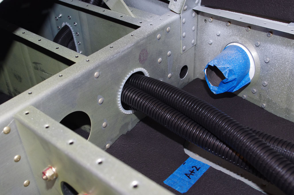
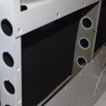 Floor panels complete, now cut and install MS21266 nylon edging grommet material on the bulkheads where power wires, antennas, and static tubes will be run.
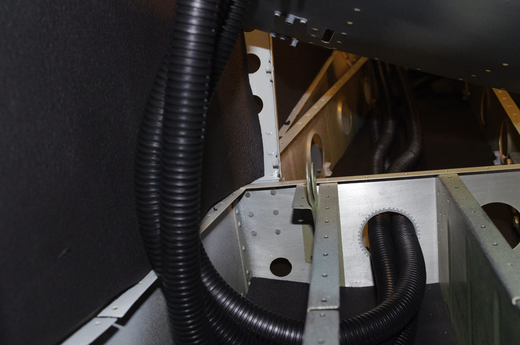
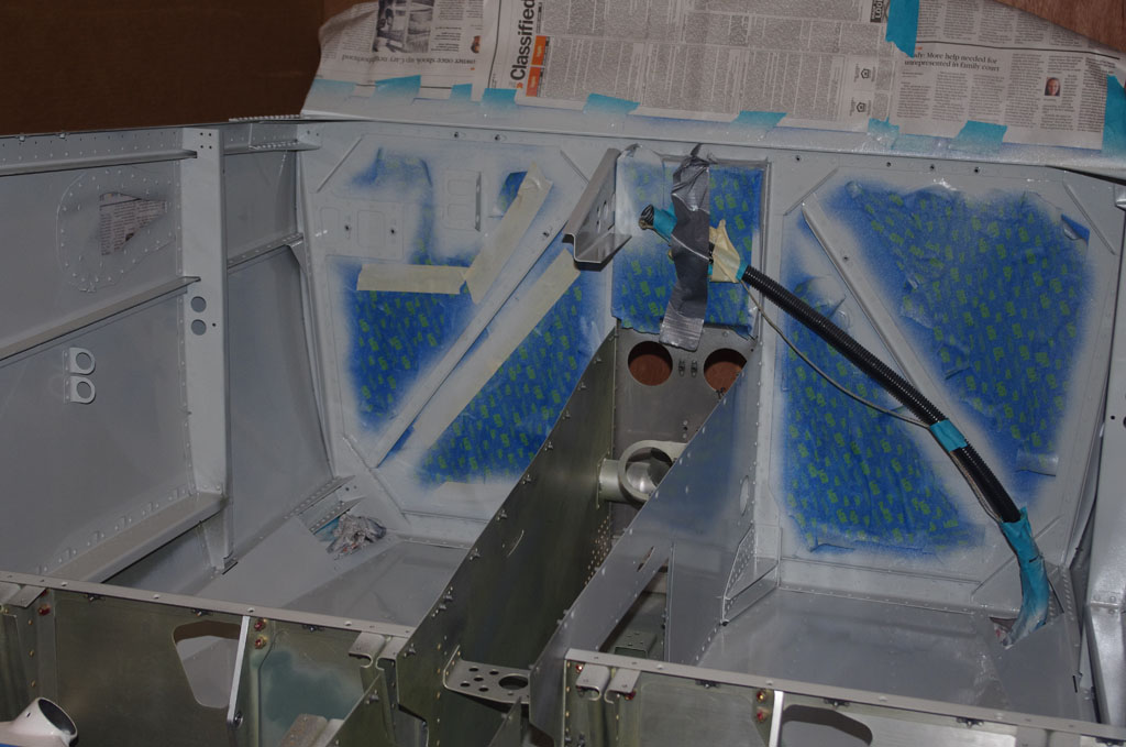
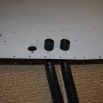 The main event – installing the 5/8″ ID black conduit. The prepared holes in the seat panel are first threaded with conduit.
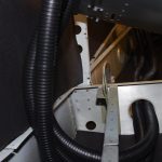
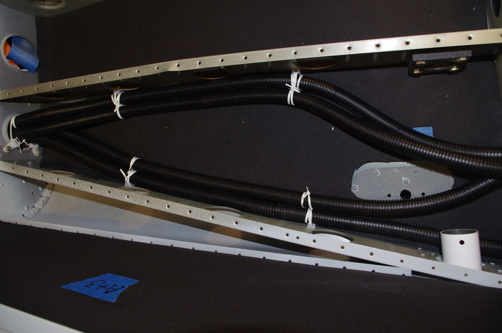
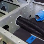 Then the conduit is run through the interior rib, and out the lightning hole under the baggage floor.
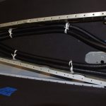
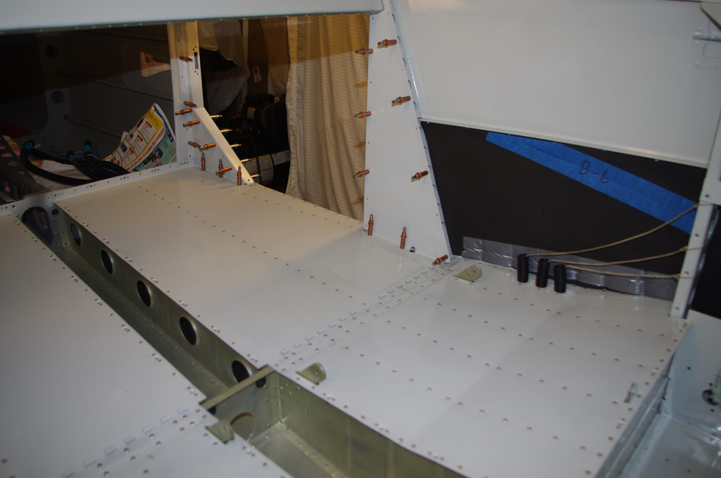
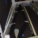 The conduit is then fastened to anchor points with 0.010″ fiberglass cable lace. Again not the prettiest outcome, but seems to hold everything together quite well.
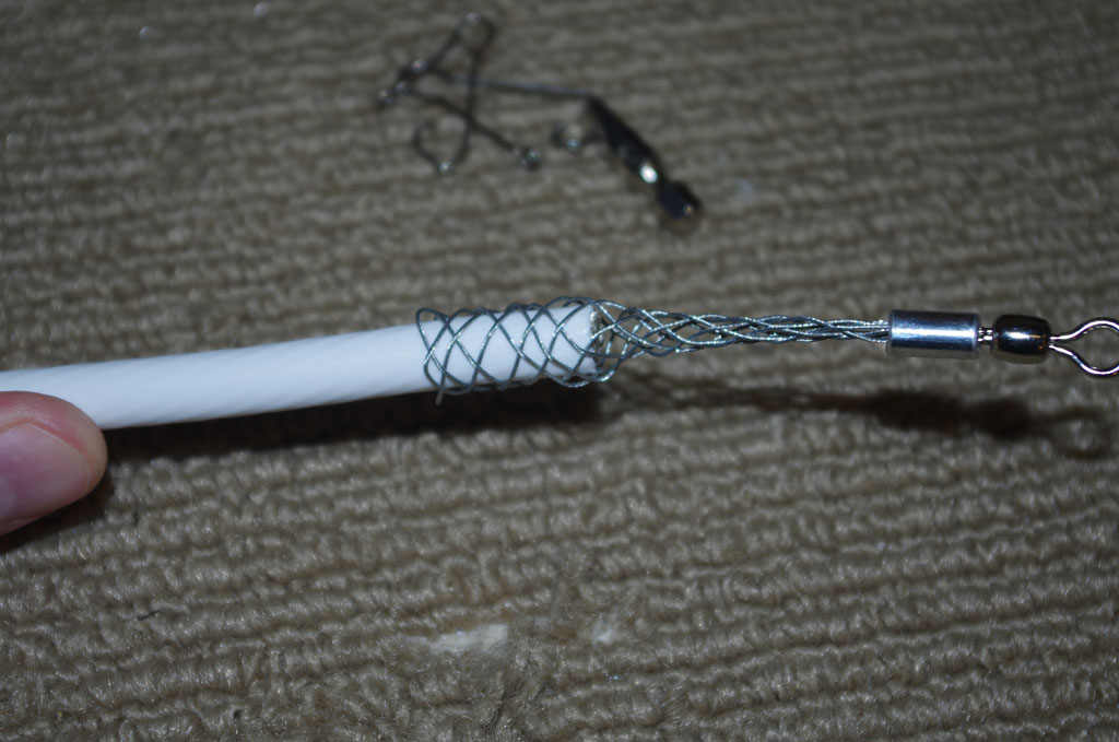
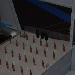 Using the packing peanut / fishing line / suction method, 2mm paracord is pulled through the installed conduit and tied to the bulkheads. These cords will later be used for pulling wires under the rear seat and under the baggage compartment. Once the seat panels are riveted in-place, no more access will be available.
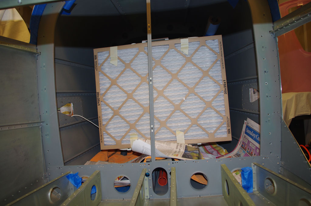
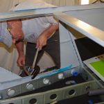 Finally for this week, I started hand riveting the side floor angles. Once these are done, the baggage floor can be permanently attached.

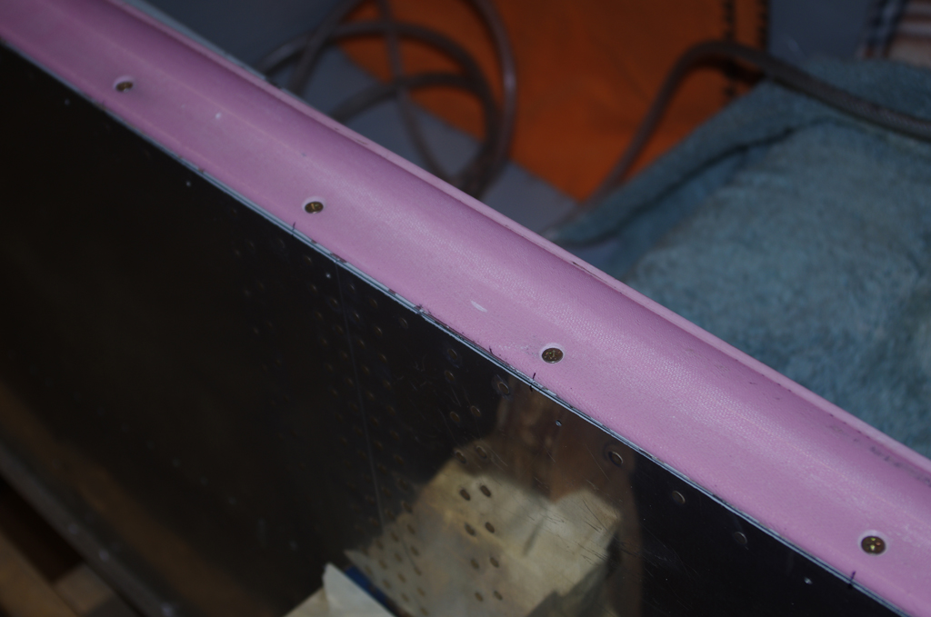
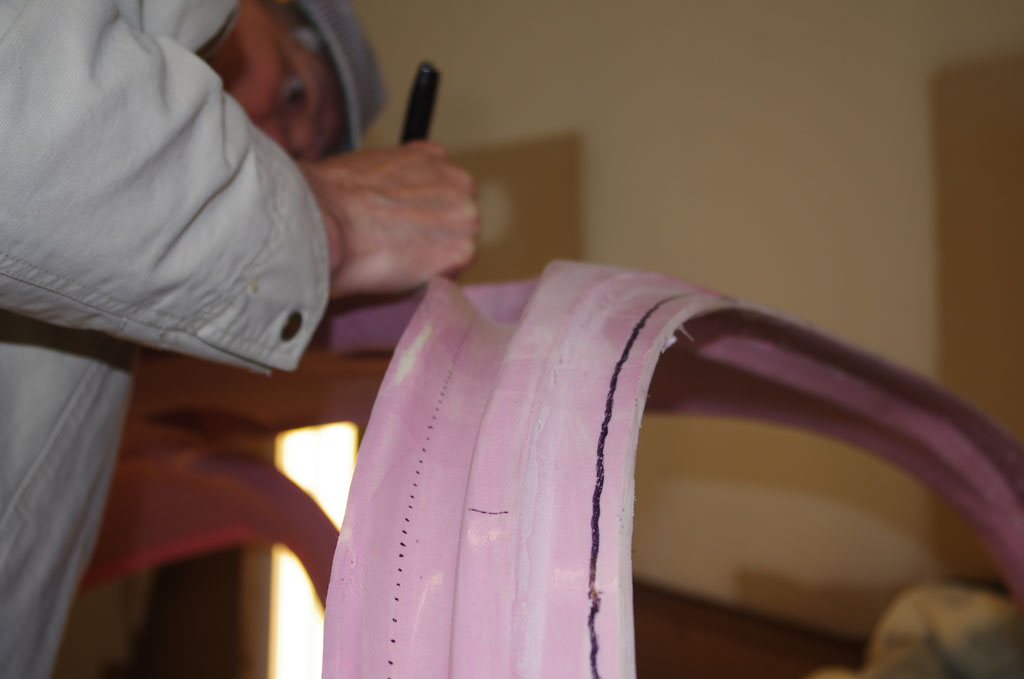
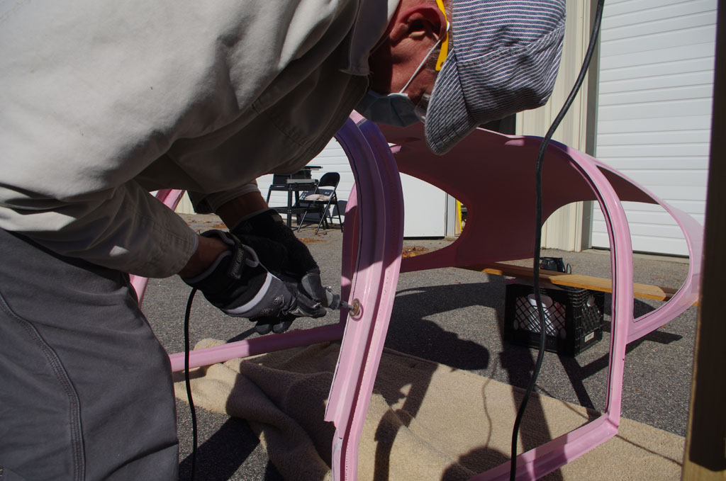
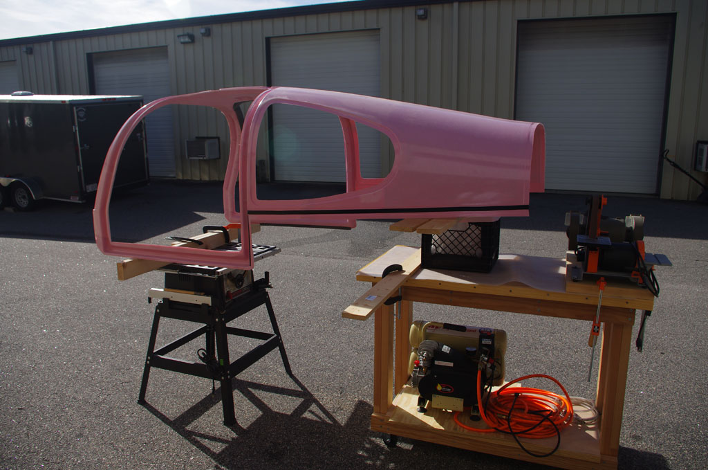
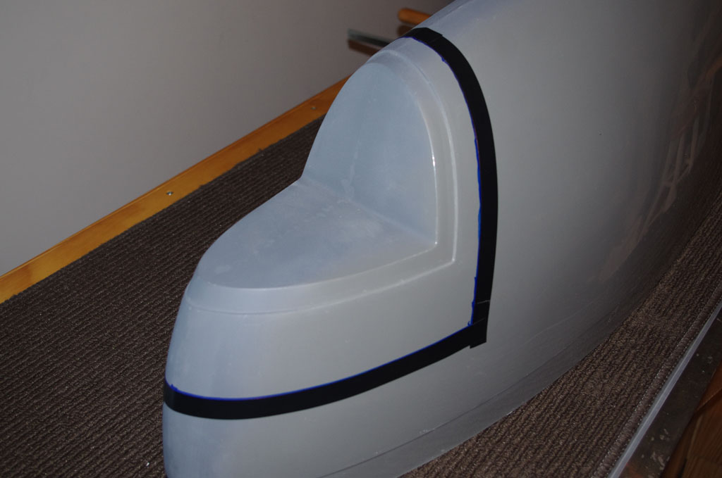
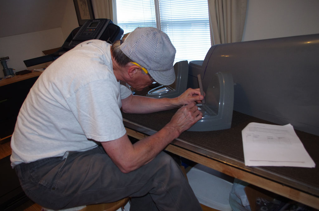
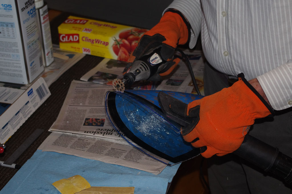
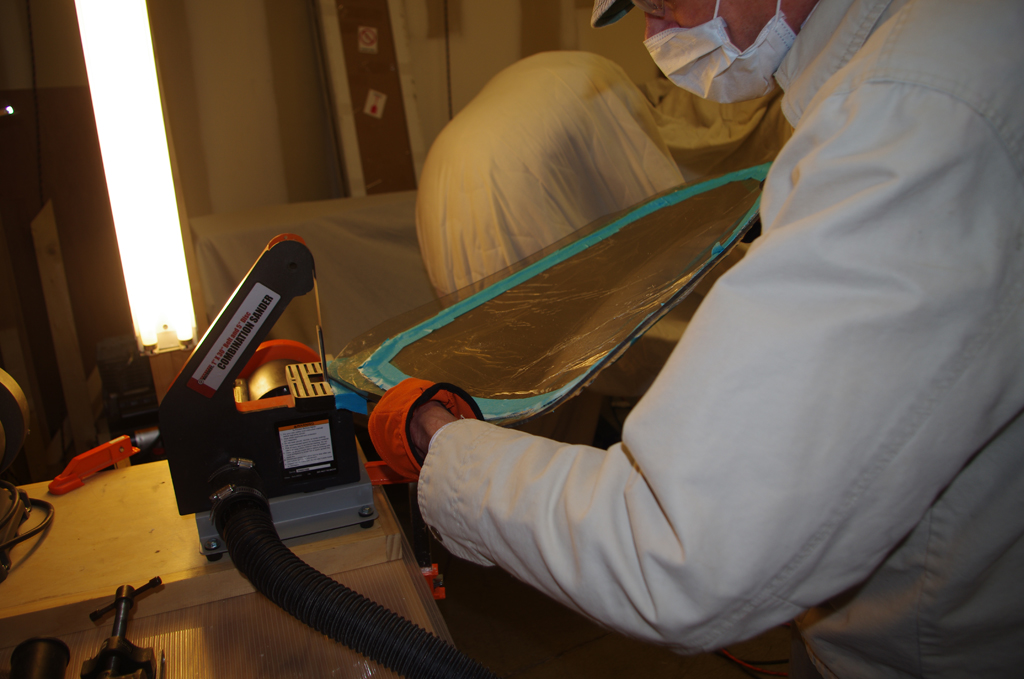 The process for the rear windows is about first getting close to the scribe line with a Dremel tool. Then using 120 grit sanding belt before hand shaving closer with 220 and polishing/rounding the edges with 320 grit.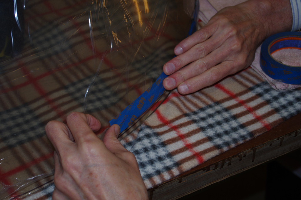
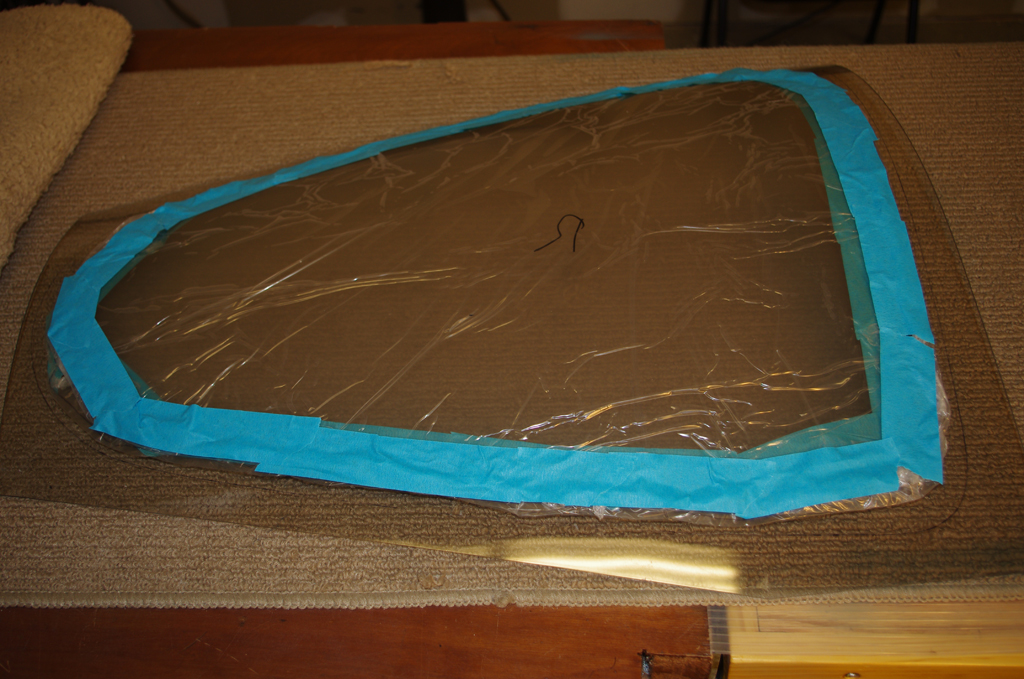
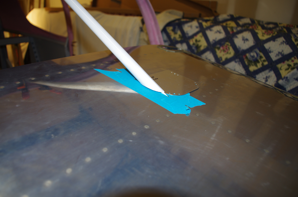
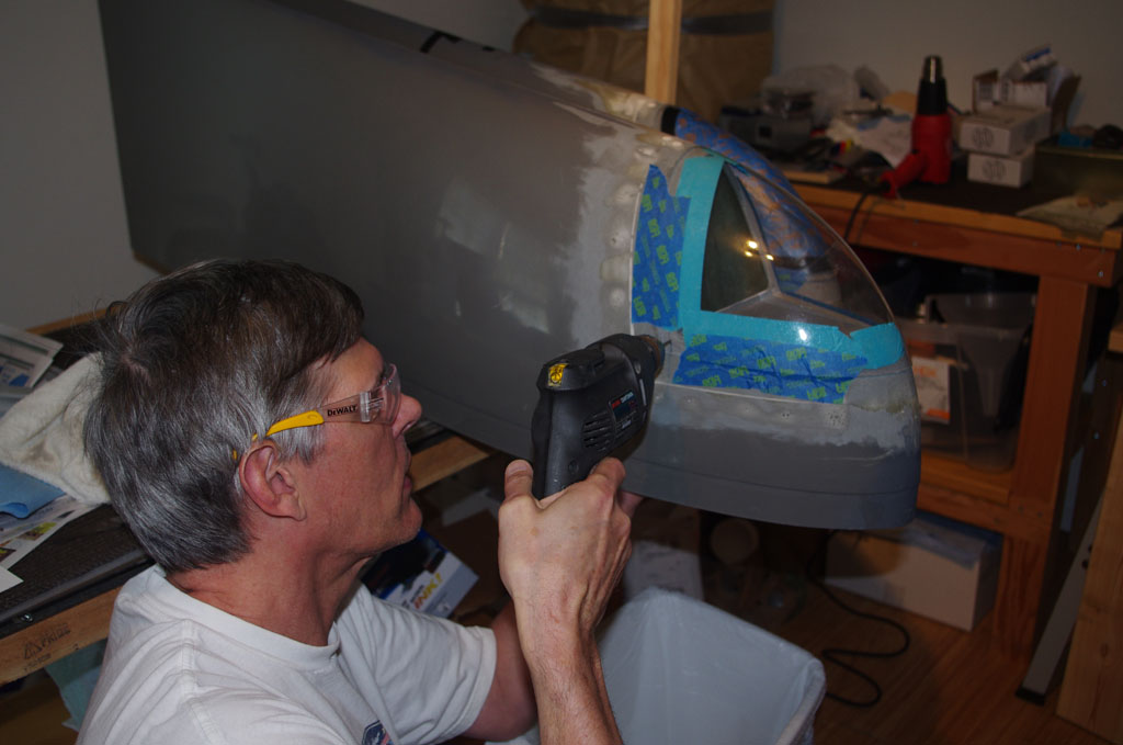
 For the windscreen first peel back the protective covering just enough to expose the previously marked scribe line.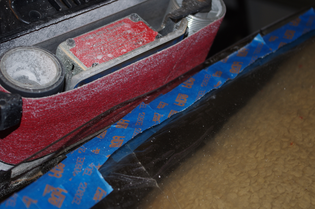
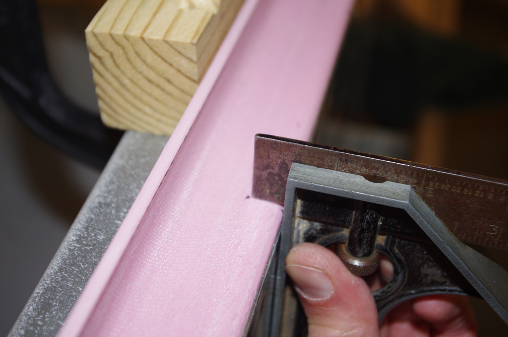
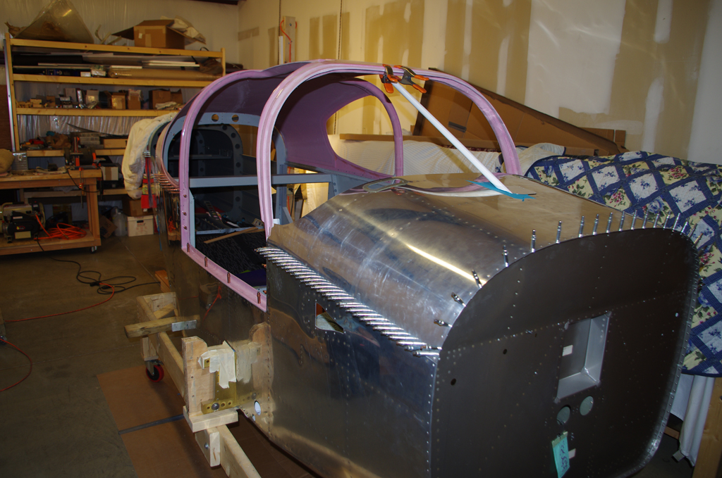
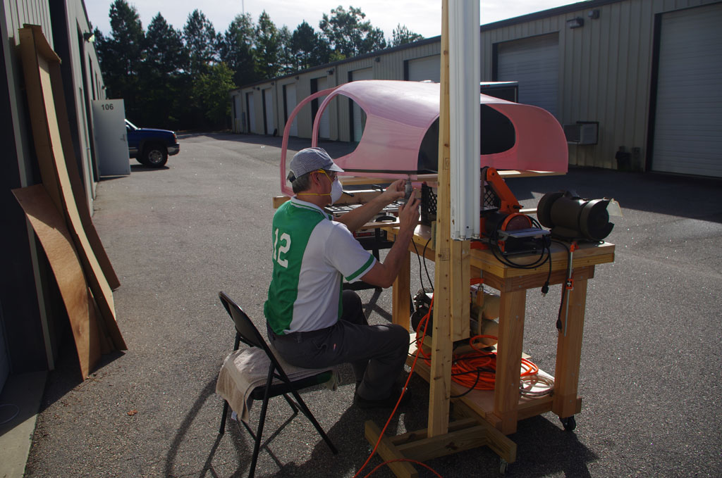
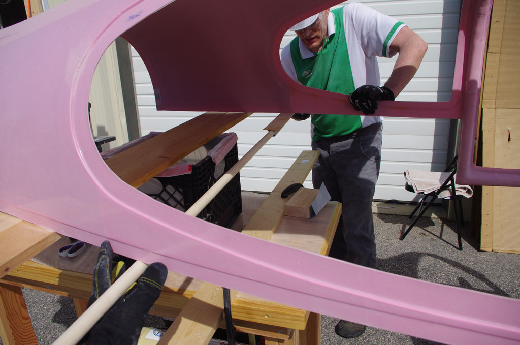
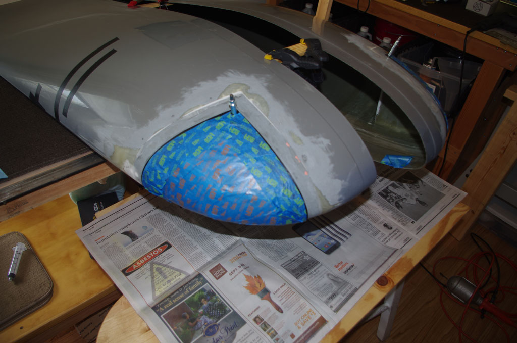
 The windscreen is a slightly different process, as it is much thicker (roughly 1/4″ Lexan or acrylic). My technical counselor advised against using a Dremel tool, saw or other cutting mechanisms (tend to cause cracking in this type/thickness material). Instead a 3″ belt sander with 80 grit paper is used to get close. Everything else is by hand.
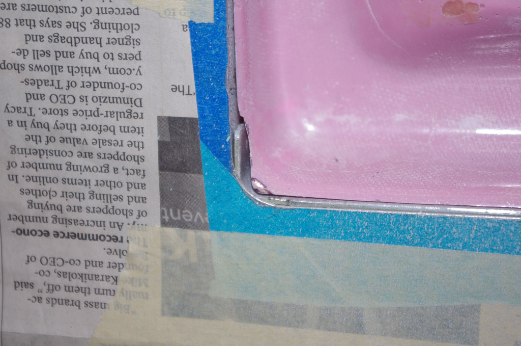
 When talking about ‘by hand’, I mean hours of edge sanding with 80 grit paper on a Great Planes sanding block. Going through Lexan this thick takes time. Check for fit, mark the high spots, and repeat over, and over, and over…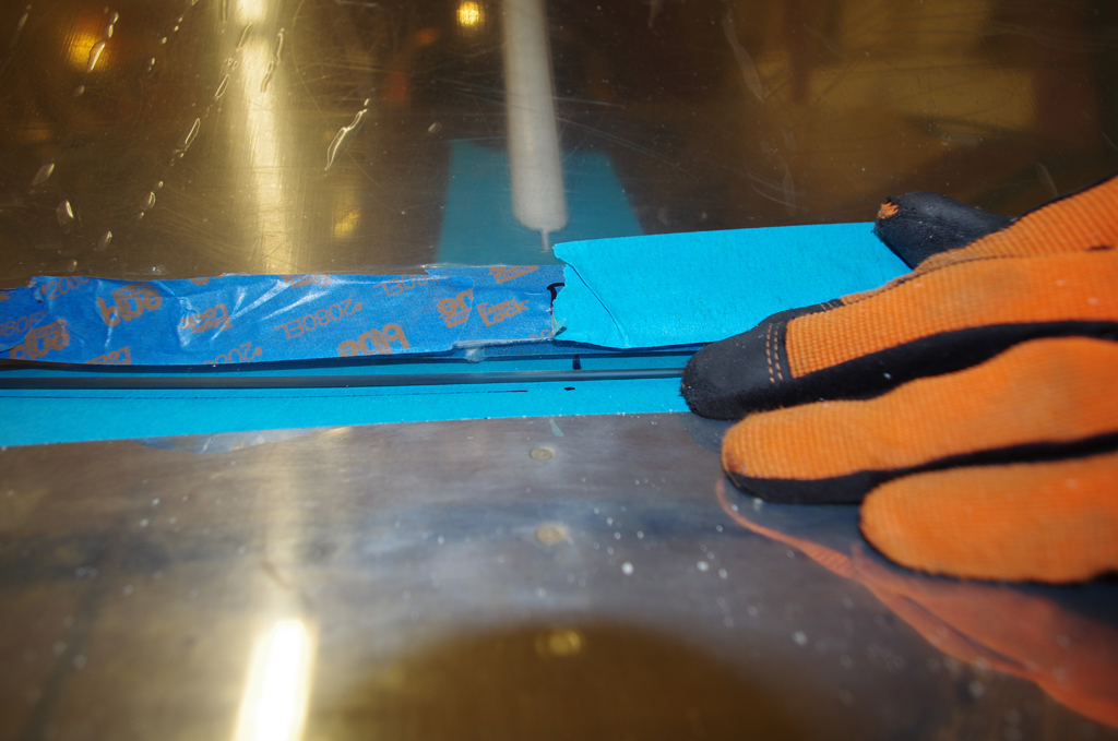
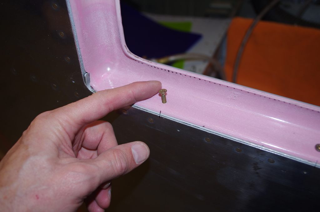
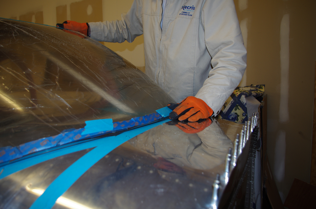 The hand shaping process requires many iterations, but this way has less danger of removing too much, too fast in the wrong places as with power tools. The final outcome is coming into shape nicely. More of the same fitting process this weekend before the edge polishing can begin.