Another power weekend finally saw the first parts riveted together!
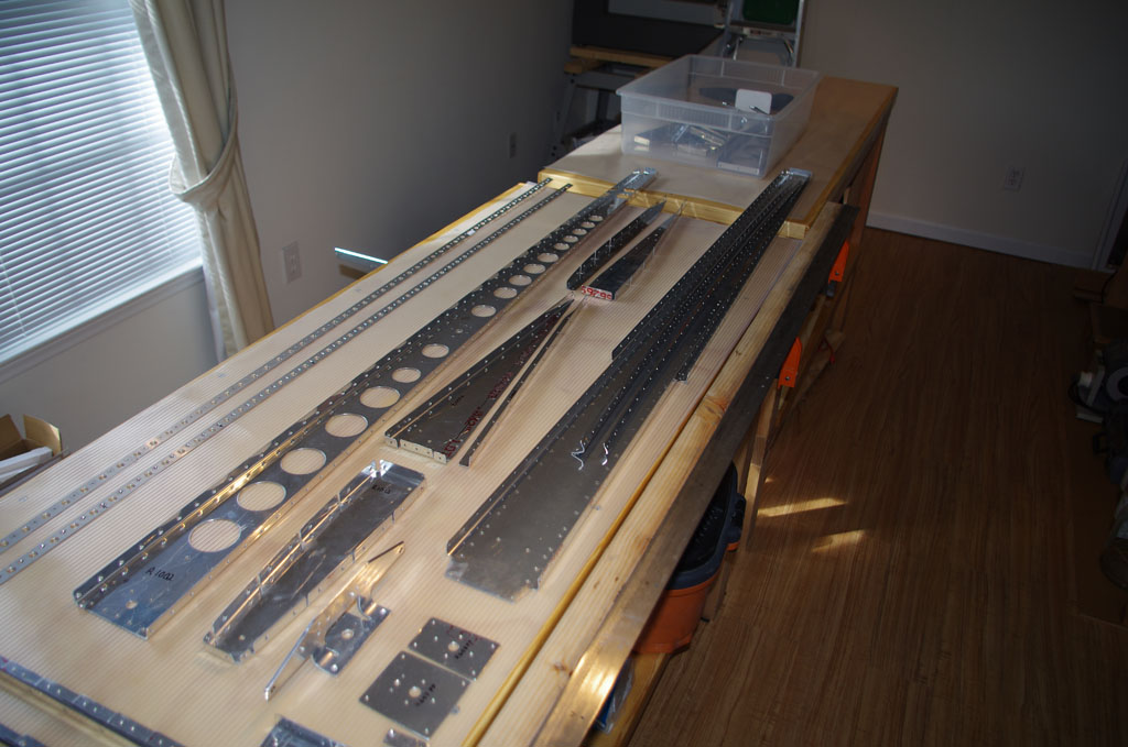
 On Saturday Rich helped me apply PreKote to the skins with a light scuffing with grey Scotchbrite. The process is simple – apply, scrub, rinse thoroughly, hang to dry.
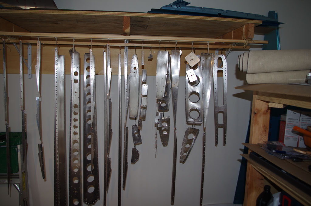
 The treated rudder skins are hanging from the dryer racks in the shed. The were left overnight to dry with a space heater and a 1000watt floodlight on to combat the near freezing temperatures. With all the devices running, the shed maintained a comfy 23 degree Celsius.
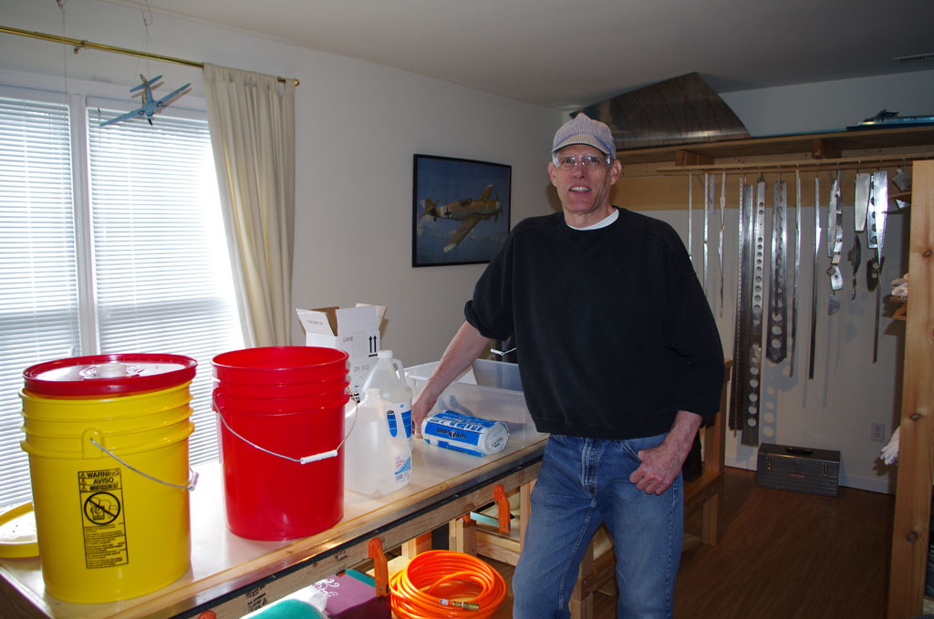
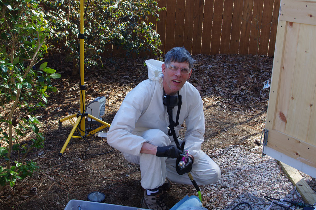 On Sunday after lunch I got suited up and ready to spray. Each time the process of preparation gets a bit smoother.
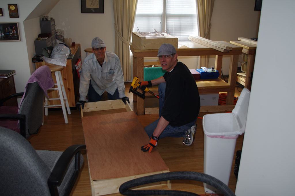
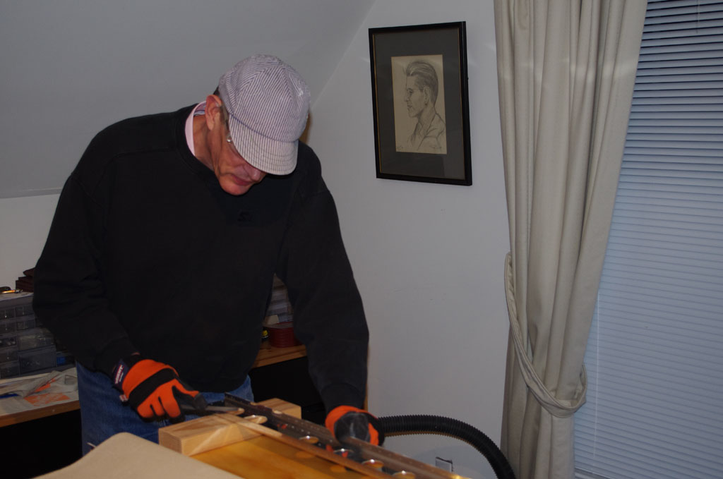
 Back in the bonus room with my first two parts to rivet in hand. Because these were not part of the Van’s build plans, I started with my custom-made doubler for the upper VS rib. Note all the primed VS and rudder parts on the drying racks in the background.
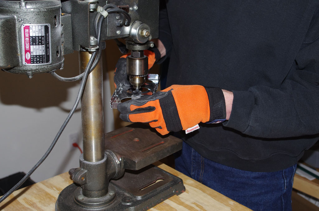
 First contact! but also brought first mistakes. The first set of squeezed rivets went so well, I overzealously put a rivet in the lower right drilled hole. The three in this row are supposed to attach to the forward VS spar. Okay, so used the rivet removal tool for extraction.
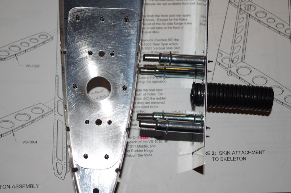
 Just to prove I can make more mistakes, here is a closeup of the final rib combination. Close examination shows the forward nut plate rivets are slightly bent inward. I was using the Main Squeeze tool properly, but with driving bits too short. This caused the C-yoke to contact the nut body at the end of the squeeze, forcing the small angle on the rivet. By using taller driving bits on the second nut plate, I got full clearance on the nut body – thus no contact, no angle and a resulting smooth surface.
 Had only the nut plate been slightly bent, I would have drilled out and replaced it. However, the doubler was also impacted and further rework would probably have done more harm than good. This is one of those occasions where the outcome is fully functional, but not esthetically perfect in the eyes of the builder.
Overall this was a great learning experience, and hopefully the beginning of a constantly improving build process.