Category Archives: Custom Elements

Cabin Doors, Custom Parts

This summary covers a long period after Airventure, and prior to Labor Day.

The hinges finally can back after being chomed.  The results are good, and primarily based on the degree of preparation sanding I put into them beforehand.  Hinge pins are cut to length from stainless steel AN3-21 bolts.


Hinge pin locations are covered with resin, then sanded smooth.


The sand, resin, repeat process took a long time to get the surfaces just right.


Once the doors were ready, a batch of alodined parts was also prepared to prime/paint at the same time.


Tal’s paint booth was used to spray the doors and the parts.


HINGE COVERS

After painting the doors a build of custom hinge covers is needed to provide a good seal to the McMaster weatherstrip. Some modeling clay was used to partially fill the hinge pockets.


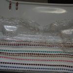
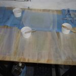
Then a few sheets of fiberglass were prepared, then pressed into position while still flexible.  Fitting and flush mounting remain after the sheets dry.


OVERHEAD CONSOLE / GPS ANTENNA MOUNT

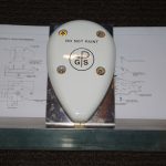
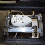
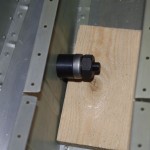
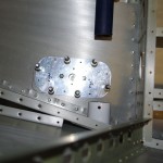
I would like to have the GPS antenna for the Garmin GTN650 located under the canopy. However, the antenna attachment is too deep to fit in the gap between the canopy and the overhead console.  A custom cover was procured via 3D printing from AeorSport Products.


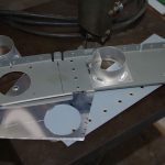
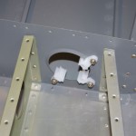
A mounting platform for the antenna itself was made from spare aluminum angle and sheets.


The platform is hinged, so exact angle with airplane centerline and flight angle can be achieved.


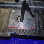
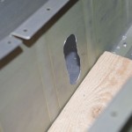
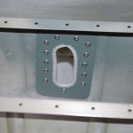
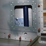
The hole for the custom cover is fabricated in the rear access panel.


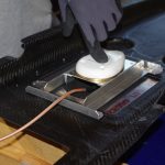
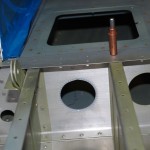
Here is the final test fit showing the configuration of the cover, mounting bracket and antenna. Once the console is bonded to the canopy, the bracket can be permanently installed.

COM2 Antenna Plate (2)

This week saw another set of clean-up activities – things started in the past, but finally with time to address.  Primary among these was final attachment of the COM2 antenna plate to the upper tailcone skin.
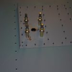
IMGP6649Step one is Pro-Seal around the major antenna holes and fasten tightly with clecoes.  After drying overnight, the excess sealing material was removed and dimples cleaned out ready for riveting.
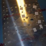


IMGP6659I decided to back rivet all locations with a 4″x6″ plate obtained from Cleveland Tools for this purpose.  To avoid the previously committed sin of slipping off the plate during riveting, this time I line up the plate in a known position by marking the antenna holes with a black Sharpie.  By always keeping the holes aligned, I was assured plate would always be under the rivet with plenty of space on either side.
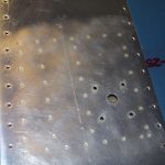


IMGP6664The outcome looks good. A bit of Scotchbrite preps the skin to accept priming.
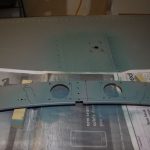


IMGP6670The backside of the antenna plate and the newly deburred holes in the baggage bulkhead are primed with SEM self-etching primer to cover any bare spots.


Next up was attaching the two static ports (one left and one right) to the rear tailcone skins.  Wooden jigs were made to clamp the ports in  position while the Pro-Seal drys.  Some folks use rivets and/or the Pro-Seal, but my experience is the Pro-Seal should be strong enough to hold by itself.
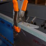
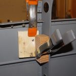
IMGP6644IMGP6646Front and back photos of the static ports while the Pro-Seal drys.


The baggage door parts were primed and painted in earlier posts.  The outer frame and hinges were then riveted together for proper alignment.  With the inner and outer panels cloeced into place, the frame now has the appropriate configuration and rigidity to final fit the outer panel to the baggage door opening in the fuselage side skins.  A gap of about 1/8″ all around is desired to allow a tight fit, but enough room to close freely.
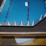
IMGP6666Here the outer edge of the bottom and right sides are marked with a Sharpie to final dimensions. The standard hand file and Scotchbrite process was used to complete the shaping.
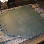


IMGP6667The inside surface of the outer panel is also primed with SEM self-etch. Next up for this piece is final paint with the BAC707 used for the cockpit interior.


Finally, I had purchased a $20 grinder from Craigslist earlier in the year.  It ran okay, but heated up quickly when in use.  I decided to replace the 6202-2RS bearings with a higher precision ABEC 3+ variety. Why – this is definitely overkill.  Well it only cost $10 for two of them, and I was curious whether it would make any difference.  In addition, the whole topic of bearing selection was a new and interesting topic for me to research.
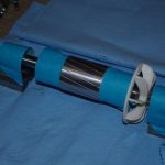
IMGP6654To replace the bearings, the outer housings are removed with a pulley puller, then the bearings.  This leaves the raw shaft and stator with fan attachment.  The flaking insulation of the stator was removed, then sprayed with electrical insulation varnish.  Here is the cleaned shaft prior to treatment.
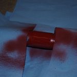


IMGP6655The shaft was placed on two V-blocks received from Rich at the estate sale.  The shaft was rotated slowly during the spray treatment.
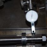


IMGP6656Time for some more overkill.  Since I already had the shaft out, I decided to measure with my new test indicator and stand obtained on eBay for $12.50!  Nice price and the setup worked great.
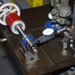


IMGP6658The indicator itself is supposed to read 0.0005″ increments.  The outer portion of the shafts vary about 0.002-0.003″, not bad, but when multiplied by the diameter of the grinding wheels, the runout is quite visible on the wheel surfaces.  The deviation on the shaft between the bearings is about 0.010″.  These numbers don’t mean much as no adjustments were made to the shaft bend.  However I am trying to use this information to gain some experience on tolerances.  The overall outcome is a smoother running and cooler motor.


I then used the test indicator on my drill press chuck – almost not detectable, which means the unextended chuck is <0.0005″.  Outstanding, but the proper test of drill press runout is fully extend the quill and measure at the end of a 4″ machinist dowel.  Since my Delta 17-900 drill press does not have a quill stop, this will be a two-man job to measure at a later date.


Sound Damping and More

This week saw a number of miscellaneous activities completed.  The main work involved spraying foam fire block material under the forward floor panels, mainly for sound damping purposes.  Other items included conduit tie-down locations and 2″ air vent hole punching.
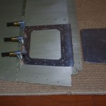
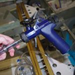
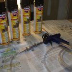
IMGP6604IMGP6611I borrowed a specialized gun for Fomo products from my friend Tal.  An extension was fashioned with Tygon tubing to insert under the already fastened floor panels of the fuselage quickbuild kit.  The tubing is held in-place with two 5/8″ hose clamps.


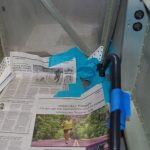
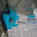
IMGP6608IMGP6607This stuff expands rapidly and is very sticky.  I tried to cover large sections of the exterior surfaces for fear of getting this stuff all over.


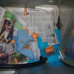
IMGP6638IMGP6640Once out the the nozzle, the foam becomes unruly and difficult to place in the right areas.  Despite my best efforts to contain the stuff, it still wound up in undesired place.  Notice how much it grew right out of some holes.


IMGP6642IMGP6643After removing the tape and paper, the expanded foam coming out is visible in a few spaces.  The results from a sound perspective were very good.  Tapping on the floor panel results in only a dull thud – which should indicate the panel cavities are fully covered. Next up – final cleanup and get ready for interior paint!
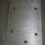
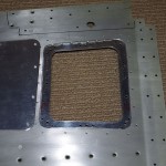
 

Another action was finalize the conduit runs from the baggage area back to the tail section.  The right side run will be used for COM antenna and magnetometer, the left side for strobes.  The intention throughout the plane is use 0.100″ fiberglass cable lace instead of plastic tie wraps to secure conduits and wires.  This method is old school and requires more effort to install, but is much more flexible and should last forever.

IMGP6617This is the back of the baggage compartment where the black conduits run forward.


IMGP6619Looking backward from the baggage ares, the Panduit nylon stand-offs can be seen in the lightning holes on the right.  Also visible are the smaller nylon tie downs riveted to the stiffeners.


IMGP6623The final stand-off is being install in the rear bulkhead.


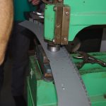
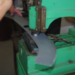
Finally, my technical counseller Terry Gardner has a #2 Diacro punch perfect for precision setting the two air supply holes needed in the baggage bulkhead.

IMGP6625IMGP6627The punch is setup and ready to roll…


IMGP6630IMGP6636Line it up, pucker, then pull the lever.  Within milli-seconds a perfect 1.9735″ hole  is positioned exactly in the bulkhead.


IMGP6637Not the best picture, but it does shows how well the punched hole and the 2″ SCAT tubing bracket align.  Just a bit of deburring the hole edges and then good-to-go.


Spar Reinforcement Brackets (2)

After two weeks in Germany on vacation and visiting relatives, I got back to a few miscellaneous activities previously started a while back.  The first was riveting the spar reinforcement brackets into place using the excellent tandem piston, alligator rivet squeezers Rich had obtained in an estate sale.  I had refurbished the squeezer itself months back (see past postings), but did not have the appropriately sized squeezer dies for -3 or -4 rivets.  I finally located a source in Florida called Delta International and ordered the right size for the job.  They arrived on Thursday and on Saturday riveting began.

I first used the AHARS platform as an off-plane test of the squeezer.  It takes a bit of adjusting with shims to get the pressure/offset between the heads correctly for a good squeeze depth.  Plus the stationary arm of the alligator jaws must be the one with the AN470 die.  Otherwise, the shop side of the rivet will be bent or smushed down incorrectly.  With a bit of practice on the platform parts, I was able to get consistently excellent results.  So glad I continued the advice never to do something for the first time directly on the plane.

IMGP6601IMGP6602Here is the squeezing operation in progress. The alligator jaws are perfect for going around the bulkhead angles from the side.  Not sure it would even be possible with a standard C-yoke configuration give the tight space laterally along the side walls.


IMGP6600Excellent. The results speak for themselves. I love putting old tools to good use.


IMGP6597I am now getting close to priming the insides of the plane.  Beforehand though, a last set of tunnel and seat covers needs to be prepped.  Here the vinyl covered parts are staged in their appropriate locations. What follows are the standard fit, drill, deburr, and prime steps.
Rear Wire Runs (2)

This week focused on finishing the wire runs under the rear seat panel and finalizing the left inspection ports for the antenna/steps.

IMGP6377The edges of the rear seat panel are normally hidden behind a removable side cover.  This seemed like an excellent location for plunging conduit runs under the seat panel (which will eventually be permanently attached with pop rivets).


IMGP6379As with all additional hole in the plane, a reinforcement plate was fabricated the help hold the 5/8″ black corrugated conduit.  Here shows the plate clecoed in position.


IMGP6382This next series shows a repeat of the inspection port fabrication, this time on the left side near the baggage door opening.


IMGP6384IMGP6389Layout the backer described in previous posts. Drill some pilot holes, then nibble a rough opening followed by hand filing and scotchbrite smoothing.


IMGP6390IMGP6391First a picture of the rough outline, then showing smoothed, primed and ready for installation.


IMGP6393Voila.  This photo shows completed floor panels clecoed in position.  All the fabricated wire runs and inspection ports have been completed.  After months of working on customized elements for my particular configurations, I should soon be getting back to the standard plans.  Next up will be layouts of the baggage compartment panels.


Rear Wire Runs

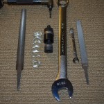
Cutting pass through holes for 5/8″ conduit under the rear seat panels is no easy chore. With the quickbuild kit, the ribs are already riveted into position about 4″ apart.  Getting a large Unibit into proper alignement is impossible.  My method was use a right-angle pneumatic drill attachment to start a small pilot hole, then enlarge with a hand file to a size big enough to accommodate a knock-out set.

IMGP6346IMGP6349The set needs a 1/2′ pilot hole, then the first punch-out occurs by tightened the 11/16″ driving screw.  On the right is the rough opening for 3 conduit runs.


IMGP6350This shows the full circle first cut, then subsequent half-moon chunks taken out progressive to make the elongated opening for the conduits.


IMGP6362IMGP6357On the left side I made the backing plate first, then used is as a template to serve as a guide.


IMGP6366IMGP6365The second opening turned out much cleaner than the first.  Of course this will not be visible to anyone after the seat panel is pop riveted closed.


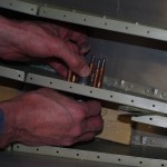
IMGP6368IMGP6369The pop rivet has a swivel head, but still there was barely enough room to operate. Slight flexing of both ribs was required to reach the bottom holes.


IMGP6372IMGP6375Final holes under the baggage floor have nylon grommets or conduit attachment brackets.

NAV Antenna Bracket (2)

After completing the oak prototype, a number of items were ordered for the final version. Blocks of acetal copolymer, 3/4″ aluminum bar, 5/8″ end mill, wiggler, some machines screw drills of various sizes, and a set of 3/16″ taps arrived for work on some precision equipment. My friend Tal is also building an RV10, so we decided to both use the same bracket design.  A few trips to another friends shop and access to milling machines and lathes was in order.

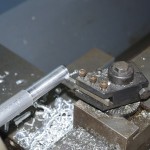
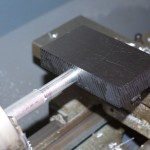
IMGP6301IMGP6302We used Tal’s bracket for the initial work, which started with using the lathe to round a 3/4″ aluminum rod down to 5/8″ to match the end mill (more on that later).  The lathe had fine adjustments down to 0.001″ and we came within a few thousandths of the mill diameter.


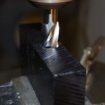
IMGP6297Next was milling the acetal block for the antenna rods. Here a wiggler is used to precisely measure the center points of the end mill holes.


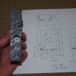
IMGP6300This shows the block and the antenna rod matched together – near perfect for a pair of amateurs.


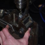
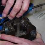
IMGP6307IMGP6309Now for drilling and tapping the rods for the actual antennas themselves. Note the special holding pieces in the vice I had gotten from Rich.


==================== February 6

Now that Tal’s bracket was completed, on to my shop for similar work. The rods had been made on the lathe beforehand, by shaping the acetal had to be done with my drill press.  This forced a slightly different approach than using the precision mill.

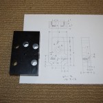
IMGP6314Here is the raw block with the planned outcome.


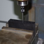
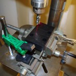
IMGP6319IMGP6320While not as accurate as the mill, my drill press is pretty good.  Using micrometers and the drill press laser guide, I was able to get close to the ideal dimensions on the rod holes on the side faces.


IMGP6326IMGP6329The through holes and corners were next. Again dimensions came out good. Note this was achieved using the X-Y drill vice also obtained from Rich from the estate sale previously mentioned.


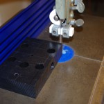
IMGP6331IMGP6332The band saw and cutting fence were used to get the rough outer dimensions of the block.  A bit work on the bench sander and the sharp edges rounded nicely.


IMGP6340IMGP6341Drill the end and top holes.


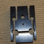
IMGP6336Close to done.


Step/Antenna Inspection Ports (3)

This weekend was about prime and rivet the inspection backers to baggage floor, then position and drill for the antenna plates for the right side installation.

IMGP6226IMGP6228IMGP6234

Add nutplates and prime with SEM aerosol can.


IMGP6239IMGP6241Top and bottom sides after completion of riveting.


IMGP6242This angle in this photo shows the 9/16″ hole drilled through the baggage floor to allow later access to the step bolt.


IMGP6243IMGP6244Two photos of the inspection plate in position.


IMGP6249IMGP6252Antenna plate for ADSB receiver drilled and clecoed in place.


IMGP6253This angle shows the antenna backer access. Getting to the coax connector and the two hold-down nuts for the antenna itself should be straightforward with this configuration.


Step/Antenna Inspection Ports (2)

These ports haven taken a long time to fabricate, basically because most of the work is being done by hand and I am quite slow with a file.  This results are usually decent for me with this method.

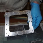
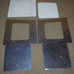
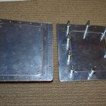
IMGP6198IMGP6207These are the roughed out plates and backers in the left photo after hand shaping and polishing. On the right are both set after initial match drilling the holding rivet and nutplate center holes.


IMGP6208IMGP6209Using the brake to bend a reinforcement angle on the backer plates.


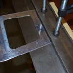
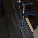
IMGP6210IMGP6214The backer is clamped to an already attached cross-brace on bottom of the baggage floor panel. This serves as the template for the rivet holes and nutplate positions.  The right photo is after all pilot holes drilled and the plate is clecoed in place.


IMGP6216IMGP6217The inspection plate itself is clecoed to the top of the baggage floor to trace an outline hole.


IMGP6218IMGP6219Now for the normal progression – pilot holes, nibble base outline, rough file, finish file, final polish with Scotchbrite.  Again everything is done by hand at this point.


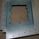
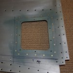
IMGP6223IMGP6225The backer plate is nearly finished.  Adding the nutplates and priming are the remaining step before riveting into place.  These photos are prior to final attachment to make sure the alignment with the baggage floor, cover panels, and step brackets are all good.


Step/Antenna Inspection Plates (1)

The baggage floor panels will eventually be riveted in place, making later access to the step holding bolt or ADSB/transponder antennas impossible. To rectify this situation two inspection holes (left and right) need to be fabricated.  In addition to considering the layout defined by the quickbuild kit, I will make a hole big enough for my fairly large hands.  A hole roughly 5″ x 5″ is needed for comfortable access.

IMGP6197The shows the right baggage floor panel in position just aft of the rear seat angle bracket. Notice the numerous rivet locations already laid out in the quick-build kit. The inspection plates need to avoid the ribs and reinforcing brackets already there.


IMGP6050With the panel out of the plane a proposed inspection port geometry is marked on paper first, then transferred onto .025″ sheet for evaluation.  This picture and the next section show a layout only about 4″ deep, not enough for my hands.  I eventually lengthened the plate to about 6 inches.


IMGP6053

The reinforcement plate layout shows the approximate location of the step bolt on the left, and the ADSB antenna fasteners.  The final larger plate should have good access to these locations.


IMGP6185IMGP6190Here I am using another of Rich’s fantastic trickle-down tools (Crafstman Scroll Saw) to rough out the reinforcement plate for the inspection panel.


IMGP6191After the center portion is roughed out, back to hand-filing and shaping on the reinforcement plate.